Cirkit Designer
Your all-in-one circuit design IDE
Home /
Project Documentation
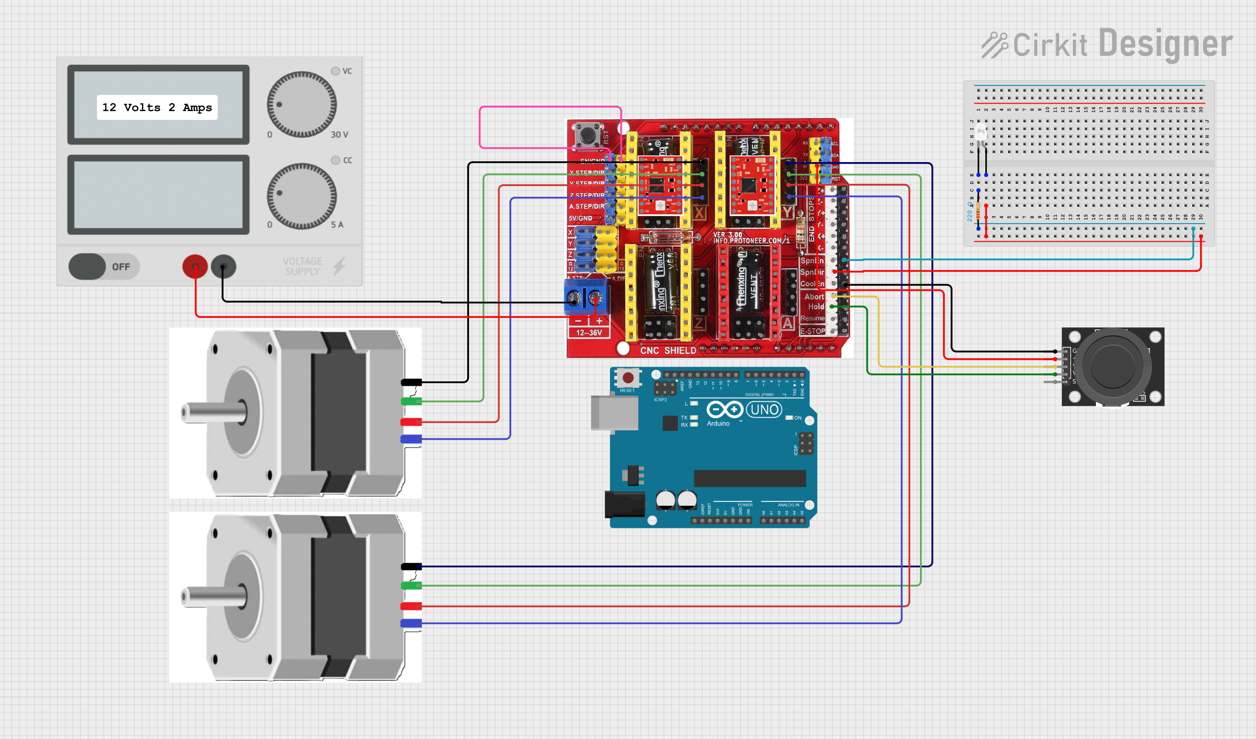
Arduino CNC Machine with Joystick Control and LED Indicator
Circuit Documentation
Summary
This circuit is designed to control a CNC machine using a joystick module. The X and Y axes of the joystick control the X and Y motors of the CNC machine. An LED is used as an indicator, turning on when the spindle direction is active. The circuit includes a power supply, a CNC shield, stepper motors, a joystick module, an LED, resistors, and an Arduino UNO microcontroller.
Component List
NEMA23 Stepper Motor
- Pins: A+, A-, B+, B-
- Description: Stepper motor used for precise control of the CNC machine's movement.
KY-023 Dual Axis Joystick Module
- Pins: GND, +5V, VRx, VRy, SW
- Description: Joystick module used to control the X and Y axes of the CNC machine.
CNC Shield V3 Engraving Machine Expansion Board
- Pins: EN, GND, x.Step, DIR, Y.Step, Z.Step, A.Step, 5V, COM, V+, End Stop X-, End Stop Z+, End Stop Z-, End Stop Y+, End Stop Y-, SpnEN, SpnDir, CoolEn, Abort, Hold, Resume, E-Stop, Y.Motor A+, Y.Motor A-, Y.Motor B+, Y.Motor B-, RST, SDA, SCL, RX, TX, 3V3, X.Motor A+, X.Motor A-, X.Motor B+, X.Motor B-, Z.Motor A+, Z.Motor A-, Z.Motor B+, Z.Motor B-, A.Motor A+, A.Motor A-, A.Motor B+, A.Motor B-, Enable, MS1, MS2, MS3, RESET, Sleep, Step, Direction, VDD, 1B, 1A, 2A, 2B, VMOT, M0, M1, M2, d12, A Drive Step and Direction, Z Drive Module Setp D4, Y Drive Module Setp D3, X Drive Module Setp D2, Set X Drive Module Dir D5, Set Y Drive Module Dir D6, Set Z Drive Module DIR d7, D13
- Description: Expansion board for controlling the CNC machine.
Power Supply
- Pins: +, -
- Description: Provides power to the circuit.
Resistor
- Pins: pin1, pin2
- Description: 220 Ohms resistor used for current limiting.
LED: Two Pin (white)
- Pins: cathode, anode
- Description: LED used as an indicator.
A988 DRIVER
- Pins: VMOT, GND, 2B, 2A, 1A, 1B, VDD, EN, MS1, MS2, MS3, RST, SLP, STEP, DIR
- Description: Stepper motor driver.
Arduino UNO
- Pins: UNUSED, IOREF, Reset, 3.3V, 5V, GND, Vin, A0, A1, A2, A3, A4, A5, SCL, SDA, AREF, D13, D12, D11, D10, D9, D8, D7, D6, D5, D4, D3, D2, D1, D0
- Description: Microcontroller used to control the CNC machine.
Wiring Details
NEMA23 Stepper Motor
- A+ connected to Y.Motor A+ on CNC Shield V3
- A- connected to Y.Motor A- on CNC Shield V3
- B+ connected to Y.Motor B+ on CNC Shield V3
- B- connected to Y.Motor B- on CNC Shield V3
KY-023 Dual Axis Joystick Module
- GND connected to GND on CNC Shield V3
- +5V connected to 5V on CNC Shield V3
- VRx connected to Abort on CNC Shield V3
- VRy connected to Hold on CNC Shield V3
CNC Shield V3 Engraving Machine Expansion Board
- EN connected to GND on CNC Shield V3
- GND connected to pin1 on Resistor
- COM connected to - on Power Supply
- V+ connected to + on Power Supply
- SpnDir connected to anode on LED
- Y.Motor A+ connected to A+ on NEMA23 Stepper Motor
- Y.Motor A- connected to A- on NEMA23 Stepper Motor
- Y.Motor B+ connected to B+ on NEMA23 Stepper Motor
- Y.Motor B- connected to B- on NEMA23 Stepper Motor
- X.Motor A+ connected to A+ on NEMA23 Stepper Motor
- X.Motor A- connected to A- on NEMA23 Stepper Motor
- X.Motor B+ connected to B+ on NEMA23 Stepper Motor
- X.Motor B- connected to B- on NEMA23 Stepper Motor
Power Supply
- + connected to V+ on CNC Shield V3
- - connected to COM on CNC Shield V3
Resistor
- pin1 connected to GND on CNC Shield V3
- pin2 connected to cathode on LED
LED: Two Pin (white)
- anode connected to SpnDir on CNC Shield V3
- cathode connected to pin2 on Resistor
Code Documentation
/*
 * Arduino CNC Machine with Joystick Control and LED Indicator
 * This sketch controls a CNC machine using a joystick module. The X and Y axes
 * of the joystick control the X and Y motors of the CNC machine. An LED is used
 * as an indicator, turning on when the spindle direction is active.
 */

// Pin definitions
const int xStepPin = 2;
const int xDirPin = 5;
const int yStepPin = 3;
const int yDirPin = 6;
const int ledPin = 13;
const int joyXPin = A0;
const int joyYPin = A1;

void setup() {
  // Initialize motor control pins
  pinMode(xStepPin, OUTPUT);
  pinMode(xDirPin, OUTPUT);
  pinMode(yStepPin, OUTPUT);
  pinMode(yDirPin, OUTPUT);
  pinMode(ledPin, OUTPUT);
  // Initialize joystick pins
  pinMode(joyXPin, INPUT);
  pinMode(joyYPin, INPUT);
}

void loop() {
  // Read joystick values
  int joyXVal = analogRead(joyXPin);
  int joyYVal = analogRead(joyYPin);

  // Control X motor
  if (joyXVal > 512) {
    digitalWrite(xDirPin, HIGH);
    digitalWrite(xStepPin, HIGH);
    delayMicroseconds(1000);
    digitalWrite(xStepPin, LOW);
    delayMicroseconds(1000);
  } else if (joyXVal < 512) {
    digitalWrite(xDirPin, LOW);
    digitalWrite(xStepPin, HIGH);
    delayMicroseconds(1000);
    digitalWrite(xStepPin, LOW);
    delayMicroseconds(1000);
  }

  // Control Y motor
  if (joyYVal > 512) {
    digitalWrite(yDirPin, HIGH);
    digitalWrite(yStepPin, HIGH);
    delayMicroseconds(1000);
    digitalWrite(yStepPin, LOW);
    delayMicroseconds(1000);
  } else if (joyYVal < 512) {
    digitalWrite(yDirPin, LOW);
    digitalWrite(yStepPin, HIGH);
    delayMicroseconds(1000);
    digitalWrite(yStepPin, LOW);
    delayMicroseconds(1000);
  }

  // Control LED indicator
  if (joyXVal != 512 || joyYVal != 512) {
    digitalWrite(ledPin, HIGH);
  } else {
    digitalWrite(ledPin, LOW);
  }
}
This code initializes the pins for the motors, joystick, and LED. It reads the joystick values and controls the X and Y motors accordingly. The LED is turned on when the joystick is moved in any direction.