
RFID-Activated Traffic Light Controller with Auditory Feedback Using Arduino Mega
View and Edit Project In Cirkit Designer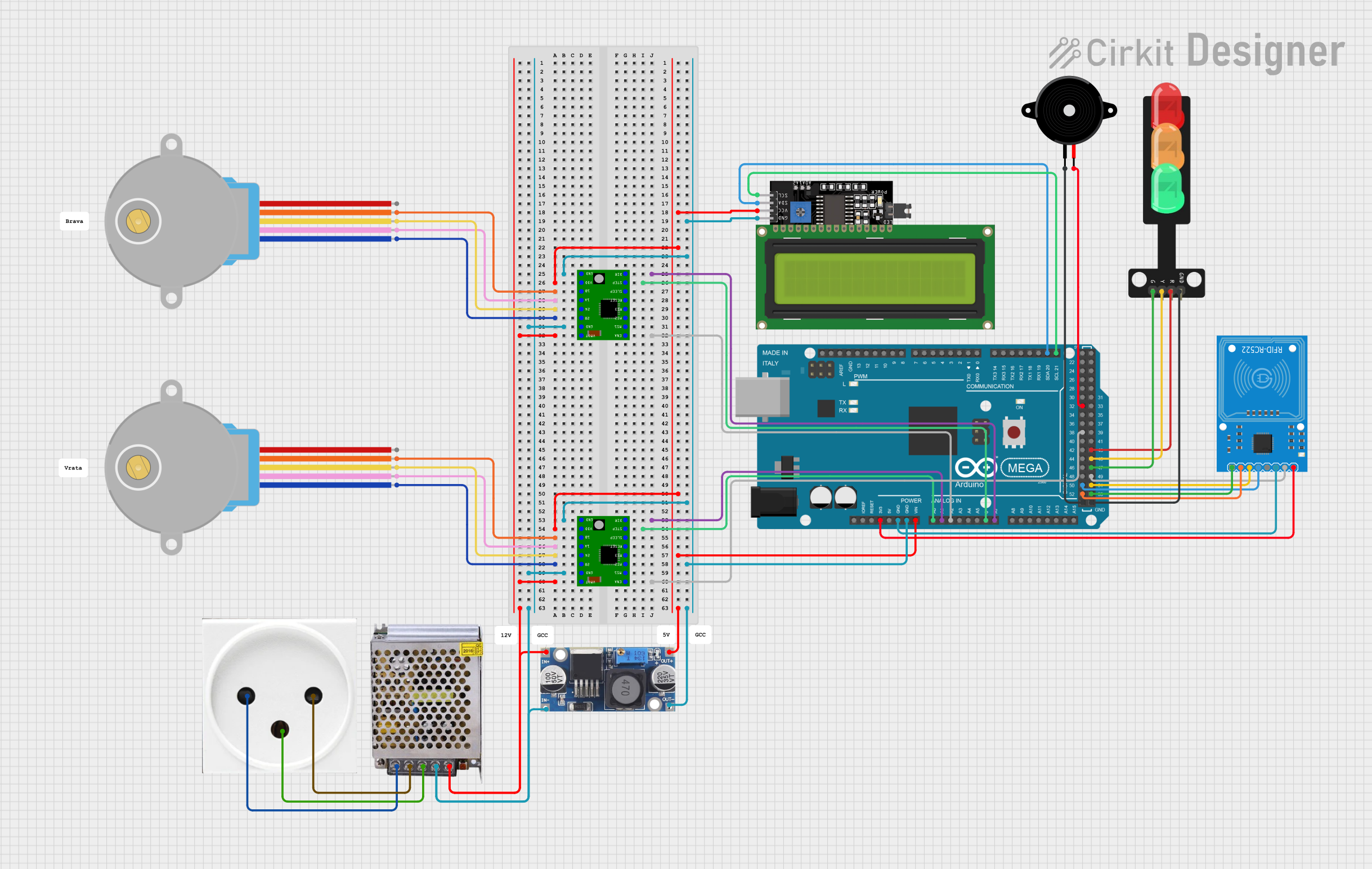
Circuit Documentation
Summary
This circuit is designed to control a system that includes two 28BYJ-48 stepper motors, an RFID-RC522 module, a traffic light indicator, a piezo speaker, and an LCD display interfaced with an Arduino Mega 2560 microcontroller. The circuit is powered by a 12V 5A power supply, and the voltage is regulated down to 5V for certain components using a 48V to 5V converter. The stepper motors are driven by A4988 stepper motor driver carriers. The RFID module, traffic light, and LCD display are interfaced with the Arduino Mega for control and data processing. The piezo speaker is connected to the Arduino for audio output.
Component List
28BYJ-48 Stepper Motor
- Description: A small, inexpensive stepper motor with a 5-wire interface.
- Pins: BLUE, PINK, YELLOW, ORANGE, RED
POWER SUPPLY 12V 5AMP
- Description: A power supply unit capable of delivering 12V DC at up to 5A.
- Pins: 220V Positive Pole (AC), 220V Negative Pole (AC), GND, GND (DC), 12V-24V Output (DC)
Power Outlet (IL)
- Description: An interface to the mains electricity supply.
- Pins: N, L, GND
Traffic Light
- Description: A traffic light indicator with three colored LEDs (Green, Yellow, Red) and a common ground.
- Pins: Green, Yellow, Red, GND
Piezo Speaker
- Description: An electronic component that emits sound when an electric current is applied.
- Pins: pin1, pin2
LCD Display 16x4 I2C
- Description: A 16x4 character LCD display with an I2C interface.
- Pins: SCL, SDA, VCC, GND
RFID-RC522
- Description: An RFID reader/writer module.
- Pins: SDA, SCK, MOSI, MISO, IRQ, GND, RST, 3.3V
48v to 5v Converter
- Description: A voltage converter that steps down 48V to 5V.
- Pins: out+, out--, in+, in--
Arduino Mega 2560
- Description: A microcontroller board based on the ATmega2560.
- Pins: Multiple digital and analog pins, power, and ground pins.
A4988 Stepper Motor Driver Carrier
- Description: A compact driver for controlling stepper motors.
- Pins: ENABLE, MS1, MS2, MS3, RESET, SLEEP, STEP, DIR, GND, VCC, 1B, 1A, 2A, 2B, VMOT
Wiring Details
28BYJ-48 Stepper Motor
- BLUE, PINK, YELLOW, ORANGE connected to corresponding A4988 driver pins.
- RED connected to power supply.
POWER SUPPLY 12V 5AMP
- 220V Positive Pole (AC) and 220V Negative Pole (AC) connected to power outlet.
- GND (DC) connected to common ground.
- 12V-24V Output (DC) connected to VMOT on A4988 drivers and in+ on the 48v to 5v converter.
Power Outlet (IL)
- N, L, GND connected to corresponding pins on the POWER SUPPLY 12V 5AMP.
Traffic Light
- Green, Yellow, Red connected to corresponding digital pins on Arduino Mega 2560.
- GND connected to common ground.
Piezo Speaker
- pin1 connected to GND on Arduino Mega 2560.
- pin2 connected to a digital pin on Arduino Mega 2560.
LCD Display 16x4 I2C
- SCL, SDA connected to corresponding I2C pins on Arduino Mega 2560.
- VCC connected to 5V power supply.
- GND connected to common ground.
RFID-RC522
- SDA, SCK, MOSI, MISO, IRQ, RST connected to corresponding SPI pins on Arduino Mega 2560.
- 3.3V connected to 3.3V on Arduino Mega 2560.
- GND connected to common ground.
48v to 5v Converter
- out+ connected to 5V power rail.
- out-- connected to common ground.
- in+ connected to 12V-24V Output (DC) from power supply.
- in-- connected to GND (DC) from power supply.
Arduino Mega 2560
- Multiple connections to various components as detailed above.
A4988 Stepper Motor Driver Carrier
- ENABLE, MS1, MS2, MS3, RESET, SLEEP connected to corresponding control pins on Arduino Mega 2560.
- STEP, DIR connected to corresponding control pins on Arduino Mega 2560.
- GND, VCC connected to common ground and 5V power rail respectively.
- 1B, 1A, 2A, 2B connected to corresponding motor coil wires.
- VMOT connected to 12V-24V Output (DC) from power supply.
Documented Code
Arduino Mega 2560 - sketch.ino
void setup() {
  // put your setup code here, to run once:

}

void loop() {
  // put your main code here, to run repeatedly:

}
Arduino Mega 2560 - documentation.txt
(No additional documentation provided)
This concludes the documentation for the circuit. The code provided is a template and needs to be filled in with the logic required to control the components as per the circuit's intended functionality.