
Circuit Documentation
Summary
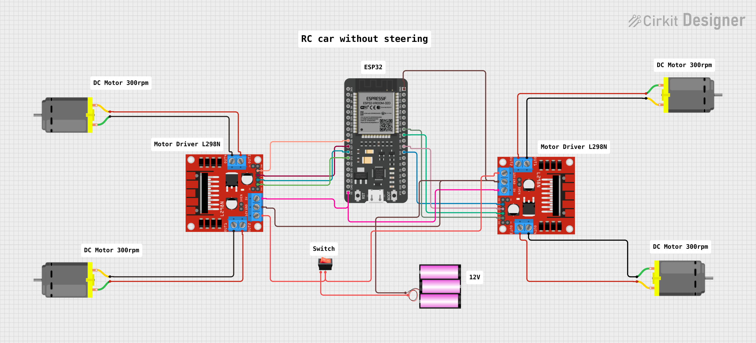
This circuit is designed to control four DC motors using two L298N DC motor drivers, which are interfaced with an ESP32 microcontroller. The motors can be independently controlled through the ESP32's GPIO pins, allowing for various operations such as changing the direction and speed of the motors. A 12V battery provides the power source for the motors and the motor drivers, while the ESP32 is powered by a 5V connection from the motor drivers. A rocker switch is used to control the power supply from the battery to the motor drivers.
Component List
ESP32 - 38 pins
- Microcontroller with WiFi and Bluetooth capabilities.
- It has a wide variety of GPIO pins for interfacing with other components.
L298N DC Motor Driver
- A motor driver module capable of driving up to two DC motors.
- It has pins for motor outputs, power supply, and control inputs from the microcontroller.
Rocker Switch
- A simple on/off switch that controls the connection between the battery and the motor drivers.
Battery 12V
- A 12V power source used to power the motor drivers and, indirectly, the DC motors.
DC Motor
- A standard DC motor with two connection pins for power and ground.
Comments
- Placeholder components that may represent annotations or notes within the circuit design.
Wiring Details
ESP32 - 38 pins
G26connected to L298N Driver (Motor Driver 1)IN4G27connected to L298N Driver (Motor Driver 1)IN3G14connected to L298N Driver (Motor Driver 1)IN2G12connected to L298N Driver (Motor Driver 1)IN15Vconnected to both L298N Drivers5VGNDconnected to both L298N DriversGNDand Battery-G19connected to L298N Driver (Motor Driver 2)IN4G18connected to L298N Driver (Motor Driver 2)IN3G17connected to L298N Driver (Motor Driver 2)IN2G16connected to L298N Driver (Motor Driver 2)IN1
L298N DC Motor Driver (Motor Driver 1)
OUT1andOUT2connected to DC Motor 1OUT3andOUT4connected to DC Motor 212Vconnected to Rocker SwitchoutputGNDconnected to ESP32GNDand Battery-
L298N DC Motor Driver (Motor Driver 2)
OUT1andOUT2connected to DC Motor 3OUT3andOUT4connected to DC Motor 412Vconnected to Rocker SwitchoutputGNDconnected to ESP32GNDand Battery-
Rocker Switch
inputconnected to Battery+outputconnected to both L298N Drivers12V
Battery 12V
+connected to Rocker Switchinput-connected to ESP32GNDand both L298N DriversGND
DC Motors
- DC Motor 1 connected to L298N Driver (Motor Driver 1)
OUT1andOUT2 - DC Motor 2 connected to L298N Driver (Motor Driver 1)
OUT3andOUT4 - DC Motor 3 connected to L298N Driver (Motor Driver 2)
OUT1andOUT2 - DC Motor 4 connected to L298N Driver (Motor Driver 2)
OUT3andOUT4
Documented Code
No code has been provided for the ESP32 microcontroller. The code would typically include the initialization of the GPIO pins as outputs and the logic to control the direction and speed of the DC motors by sending signals to the L298N motor driver's input pins.