Cirkit Designer
Your all-in-one circuit design IDE
Home /
Project Documentation
Arduino UNO Water Level Monitoring System with Buzzer and LED Alert
Circuit Documentation
Summary
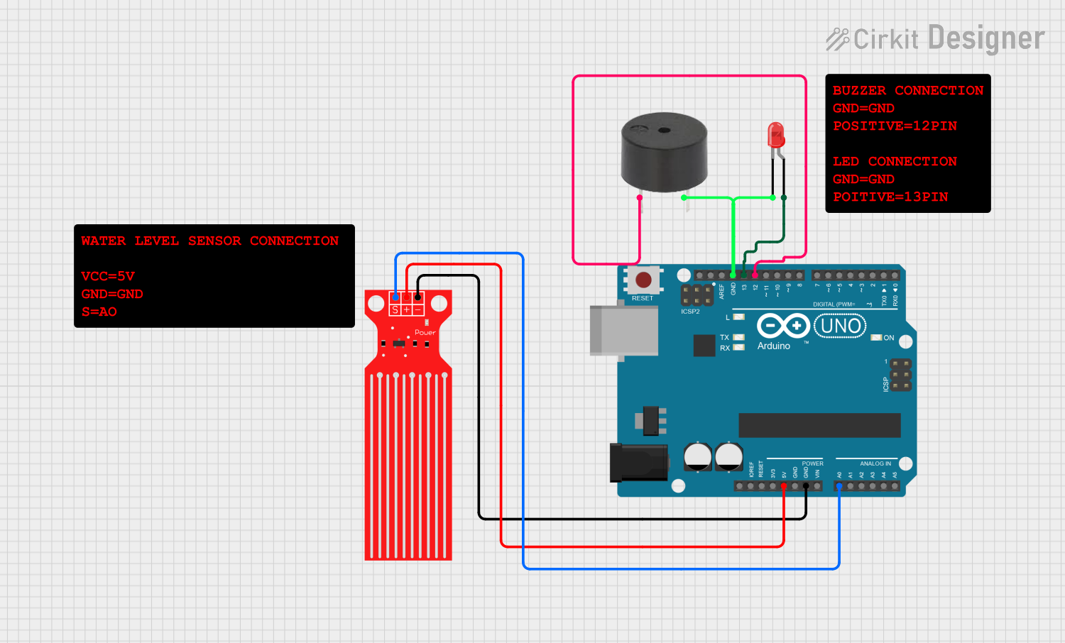
This circuit is designed to monitor water levels using a water level sensor and provide feedback through a buzzer and an LED. The system is controlled by an Arduino UNO microcontroller, which processes the sensor data and activates the buzzer and LED accordingly.
Component List
Water Level Sensor
- Pins: SIG, VCC, GND
- Description: Measures the water level and outputs an analog signal.
- Purpose in Circuit: Provides water level data to the Arduino.
Buzzer
- Pins: PIN, GND
- Description: Emits sound when activated.
- Purpose in Circuit: Provides audible feedback when certain water levels are detected.
LED: Two Pin (red)
- Pins: Cathode, Anode
- Description: Emits red light when powered.
- Purpose in Circuit: Provides visual feedback when certain water levels are detected.
Arduino UNO
- Pins: UNUSED, IOREF, Reset, 3.3V, 5V, GND, Vin, A0, A1, A2, A3, A4, A5, SCL, SDA, AREF, D13, D12, D11, D10, D9, D8, D7, D6, D5, D4, D3, D2, D1, D0
- Description: Microcontroller board based on the ATmega328P.
- Purpose in Circuit: Controls the entire system, processes sensor data, and drives the buzzer and LED.
Wiring Details
Water Level Sensor
- SIG connected to A0 on Arduino UNO
- VCC connected to 5V on Arduino UNO
- GND connected to GND on Arduino UNO
Buzzer
- PIN connected to D12 on Arduino UNO
- GND connected to GND on Arduino UNO and cathode of LED
LED: Two Pin (red)
- Anode connected to D13 on Arduino UNO
- Cathode connected to GND on Arduino UNO and GND of Buzzer
Documented Code
sketch.ino
void setup() {
  // put your setup code here, to run once:

}

void loop() {
  // put your main code here, to run repeatedly:

}
documentation.txt
This documentation provides a comprehensive overview of the circuit, including a summary, detailed component list, wiring details, and the code used in the microcontroller.