
Arduino Mega 2560-Based Robotic Hand with OLED Display and Joystick Control
View and Edit Project In Cirkit Designer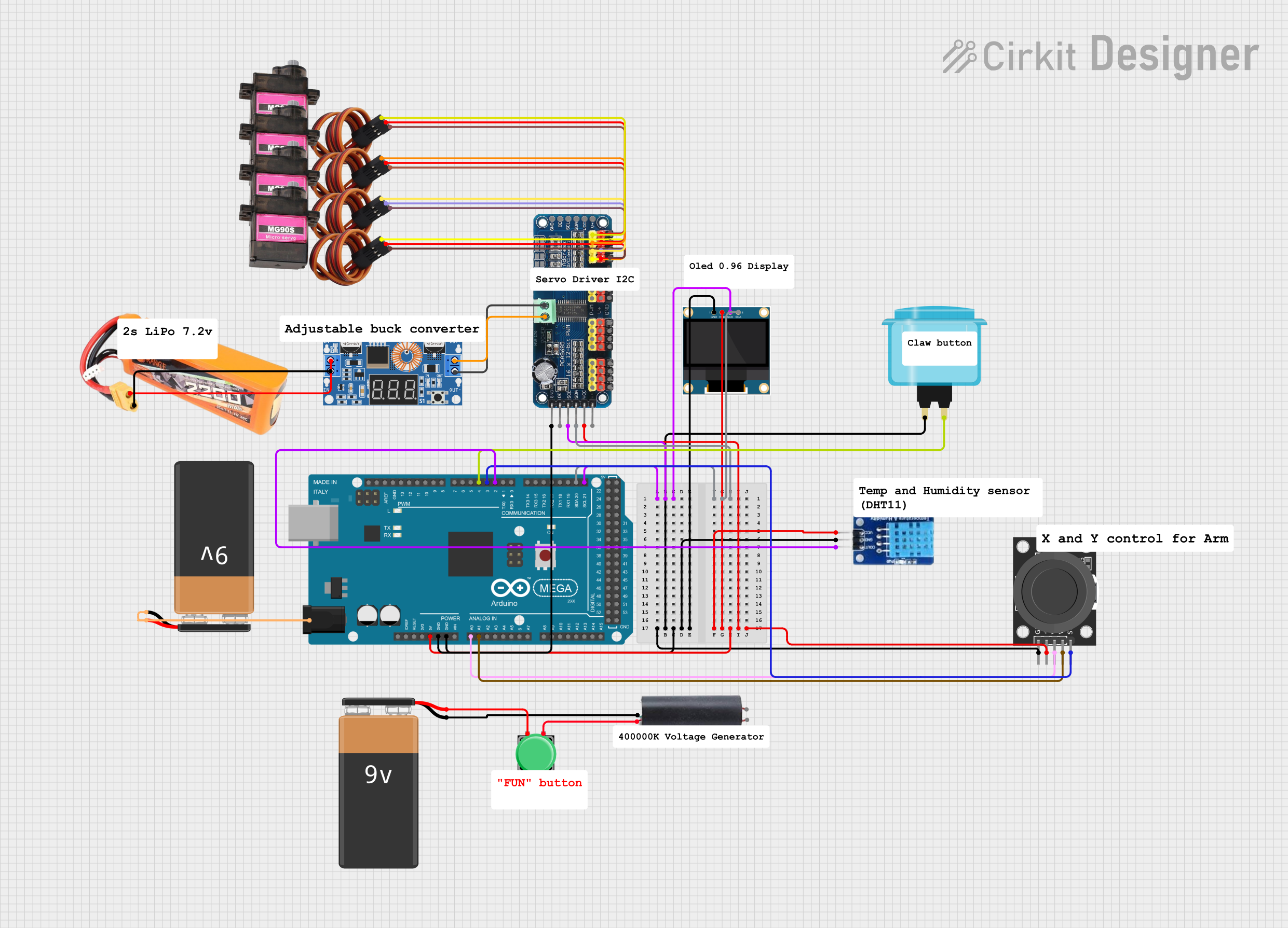
Circuit Documentation
Summary
This circuit involves an Arduino Mega 2560 microcontroller interfacing with various components including a 0.96" OLED display, a 16-Channel PWM Servo Driver, multiple MG90S servos, a DHT11 temperature and humidity sensor, a KY-023 Dual Axis Joystick Module, an Arcade Button, a Pushbutton, a High Voltage Generator, a 9V Battery, an XL4015 5A DC Buck Step-down, and a LiPo battery. The circuit is designed to control servos, read sensor data, and display information on the OLED screen.
Component List
Arduino Mega 2560
- Description: A microcontroller board based on the ATmega2560.
- Pins: IOREF, RESET, 3V3, 5V, GND, VIN, A0-A15, D0-D53, PWM pins, AREF, SDA, SCL.
0.96" OLED
- Description: A small OLED display module.
- Pins: GND, VDD, SCK, SDA.
16-Channel PWM Servo Driver
- Description: A driver board for controlling up to 16 servos.
- Pins: V+, VCC, SDA, SCL, OE, GND, Vin+, Vin-, PWM1-PWM16.
MG90S Servo
- Description: A micro servo motor.
- Pins: SIG, VCC, GND.
Pushbutton
- Description: A simple pushbutton switch.
- Pins: Pin 1, Pin 2, Pin 3, Pin 4.
High Voltage Generator
- Description: A module for generating high voltage.
- Pins: out 1, Out 2, VCC, GND.
9V Battery
- Description: A standard 9V battery.
- Pins: -, +.
XL4015 5A DC Buck Step-down
- Description: A DC-DC buck converter.
- Pins: Output +, Output -, Input +, Input -.
LiPo Battery 2200mAH 30c
- Description: A rechargeable lithium polymer battery.
- Pins: VCC, GND.
Arcade Button (blue)
- Description: A large arcade-style button.
- Pins: no name yet.
KY-023 Dual Axis Joystick Module
- Description: A joystick module with two axes and a button.
- Pins: GND, +5V, VRx, VRy, SW.
DHT11
- Description: A temperature and humidity sensor.
- Pins: DATA, GND, VCC.
Wiring Details
Arduino Mega 2560
- 5V: Connected to VCC of 16-Channel PWM Servo Driver, VCC of DHT11, VDD of 0.96" OLED, and +5V of KY-023 Dual Axis Joystick Module.
- GND: Connected to GND of 16-Channel PWM Servo Driver, GND of DHT11, GND of 0.96" OLED, GND of Arcade Button, and GND of KY-023 Dual Axis Joystick Module.
- A0: Connected to VRx of KY-023 Dual Axis Joystick Module.
- A1: Connected to VRy of KY-023 Dual Axis Joystick Module.
- D21/SCL: Connected to SCL of 16-Channel PWM Servo Driver and SCK of 0.96" OLED.
- D20/SDA: Connected to SDA of 16-Channel PWM Servo Driver and SDA of 0.96" OLED.
- D2 PWM: Connected to DATA of DHT11.
- D3 PWM: Connected to SW of KY-023 Dual Axis Joystick Module.
- D4 PWM: Connected to Arcade Button.
- 6swdw: Connected to both terminals of 9V Battery.
0.96" OLED
- VDD: Connected to 5V of Arduino Mega 2560.
- GND: Connected to GND of Arduino Mega 2560.
- SCK: Connected to D21/SCL of Arduino Mega 2560.
- SDA: Connected to D20/SDA of Arduino Mega 2560.
16-Channel PWM Servo Driver
- VCC: Connected to 5V of Arduino Mega 2560.
- GND: Connected to GND of Arduino Mega 2560.
- SCL: Connected to D21/SCL of Arduino Mega 2560.
- SDA: Connected to D20/SDA of Arduino Mega 2560.
- Vin+: Connected to Output + of XL4015 5A DC Buck Step-down.
- Vin-: Connected to Output - of XL4015 5A DC Buck Step-down.
- PWM13: Connected to SIG of MG90S Servo.
- PWM14: Connected to SIG of MG90S Servo.
- PWM15: Connected to SIG of MG90S Servo.
- PWM16: Connected to SIG of MG90S Servo.
- GND: Connected to GND of MG90S Servos.
- V+: Connected to VCC of MG90S Servos.
MG90S Servos
- SIG: Connected to PWM13, PWM14, PWM15, and PWM16 of 16-Channel PWM Servo Driver.
- VCC: Connected to V+ of 16-Channel PWM Servo Driver.
- GND: Connected to GND of 16-Channel PWM Servo Driver.
Pushbutton
- Pin 1: Connected to + of 9V Battery.
- Pin 3: Connected to VCC of High Voltage Generator.
High Voltage Generator
- VCC: Connected to Pin 3 of Pushbutton.
- GND: Connected to - of 9V Battery.
9V Battery
- -: Connected to GND of High Voltage Generator.
- +: Connected to Pin 1 of Pushbutton and 6swdw of Arduino Mega 2560.
XL4015 5A DC Buck Step-down
- Input +: Connected to VCC of LiPo Battery.
- Input -: Connected to GND of LiPo Battery.
- Output +: Connected to Vin+ of 16-Channel PWM Servo Driver.
- Output -: Connected to Vin- of 16-Channel PWM Servo Driver.
LiPo Battery 2200mAH 30c
- VCC: Connected to Input + of XL4015 5A DC Buck Step-down.
- GND: Connected to Input - of XL4015 5A DC Buck Step-down.
Arcade Button (blue)
- no name yet: Connected to GND and D4 PWM of Arduino Mega 2560.
KY-023 Dual Axis Joystick Module
- +5V: Connected to 5V of Arduino Mega 2560.
- GND: Connected to GND of Arduino Mega 2560.
- VRx: Connected to A0 of Arduino Mega 2560.
- VRy: Connected to A1 of Arduino Mega 2560.
- SW: Connected to D3 PWM of Arduino Mega 2560.
DHT11
- VCC: Connected to 5V of Arduino Mega 2560.
- GND: Connected to GND of Arduino Mega 2560.
- DATA: Connected to D2 PWM of Arduino Mega 2560.
Documented Code
Arduino Mega 2560 Code
sketch.ino
void setup() {
  // put your setup code here, to run once:

}

void loop() {
  // put your main code here, to run repeatedly:

}
documentation.txt
This documentation provides a comprehensive overview of the circuit, including a detailed component list, wiring details, and the code used in the Arduino Mega 2560 microcontroller.