
Arduino UNO and Adafruit ADS1015 Based Analog to Digital Conversion
View and Edit Project In Cirkit Designer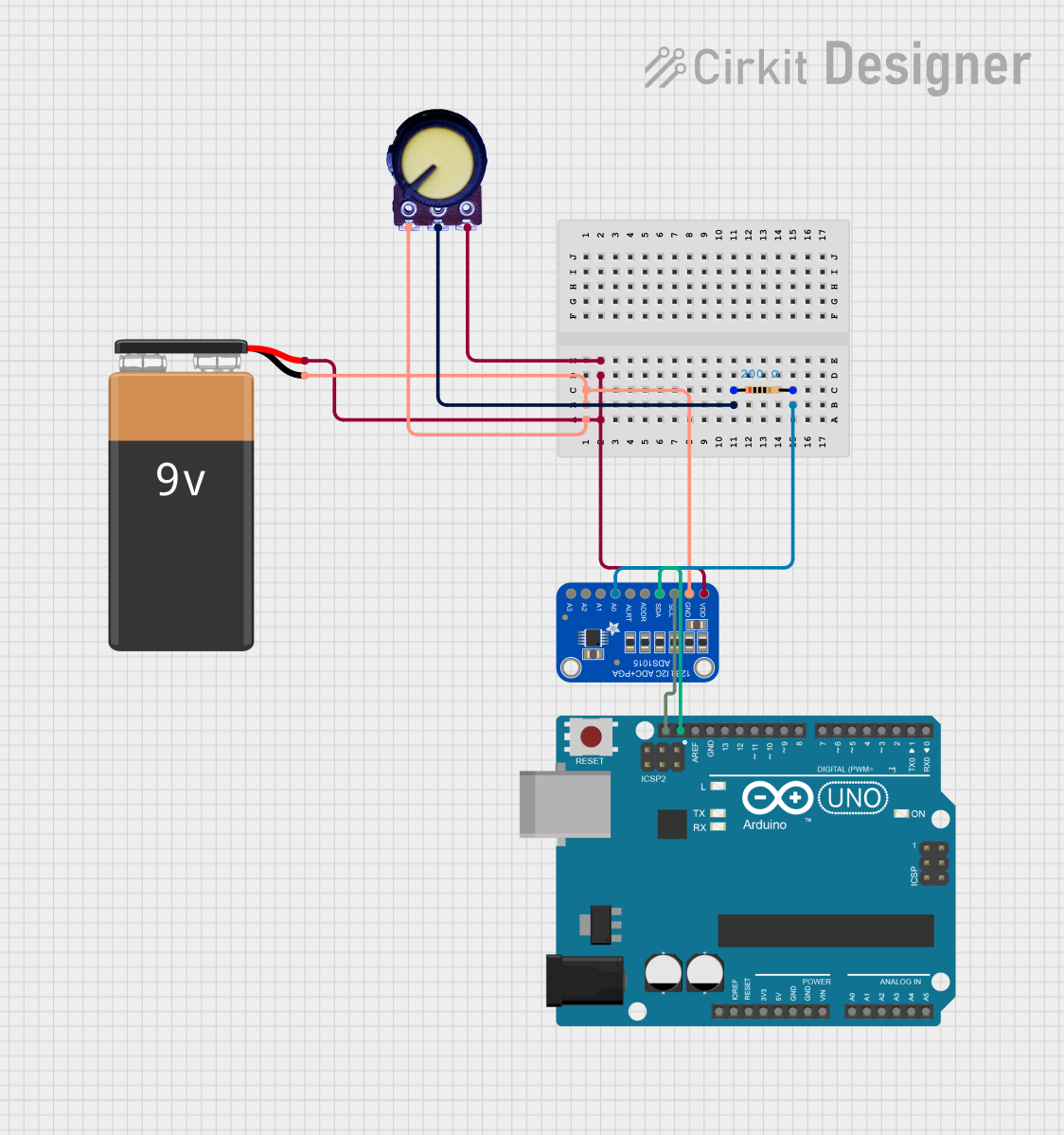
Circuit Documentation
Summary of the Circuit
This circuit is designed to read analog values from a potentiometer and convert them to digital using the Adafruit ADS1015 12Bit I2C ADC (Analog-to-Digital Converter). The ADC communicates with an Arduino UNO microcontroller over I2C. The potentiometer's output is connected to the ADC's input channel through a resistor. The circuit is powered by a 9V battery. The Arduino UNO reads the digital values from the ADC and outputs the readings to the serial monitor.
Component List
Adafruit ADS1015 12Bit I2C ADC
- Description: A precision, 12-bit, I2C-compatible analog-to-digital converter.
- Pins: VDD, GND, SCL, SDA, ADDR, ALERT, AIN0, AIN1, AIN2, AIN3
Arduino UNO
- Description: A microcontroller board based on the ATmega328P.
- Pins: UNUSED, IOREF, Reset, 3.3V, 5V, GND, Vin, A0, A1, A2, A3, A4, A5, SCL, SDA, AREF, D13, D12, D11, D10, D9, D8, D7, D6, D5, D4, D3, D2, D1, D0
Potentiometer
- Description: A three-terminal resistor with a continuously adjustable tapping point controlled by rotation of a shaft or knob.
- Pins: GND, Output, VCC
9V Battery
- Description: A standard 9V battery used to provide power to the circuit.
- Pins: -, +
Resistor
- Description: A passive two-terminal electrical component that implements electrical resistance as a circuit element.
- Pins: pin1, pin2
- Properties: Resistance - 200 Ohms
Wiring Details
Adafruit ADS1015 12Bit I2C ADC
- VDD: Connected to 9V Battery (+)
- GND: Connected to 9V Battery (-)
- SCL: Connected to Arduino UNO SCL
- SDA: Connected to Arduino UNO SDA
- AIN0: Connected to Resistor (pin2)
Arduino UNO
- SCL: Connected to ADS1015 SCL
- SDA: Connected to ADS1015 SDA
Potentiometer
- VCC: Connected to 9V Battery (+)
- GND: Connected to 9V Battery (-)
- Output: Connected to Resistor (pin1)
9V Battery
- +: Connected to Potentiometer VCC and ADS1015 VDD
- -: Connected to Potentiometer GND and ADS1015 GND
Resistor
- pin1: Connected to Potentiometer Output
- pin2: Connected to ADS1015 AIN0
Documented Code
#include <Adafruit_ADS1X15.h>
/*
 * Arduino Sketch for a simple analog to digital converter test using a
 * potentiometer. The circuit uses an Adafruit ADS1015 12Bit I2C ADC to read
 * the analog values from the potentiometer and displays the values on the
 * serial monitor.
 *
 * Circuit Connections:
 * - ADS1015 VDD to 9V Battery +
 * - ADS1015 GND to 9V Battery -
 * - ADS1015 SCL to Arduino UNO SCL
 * - ADS1015 SDA to Arduino UNO SDA
 * - Potentiometer VCC to 9V Battery +
 * - Potentiometer GND to 9V Battery -
 * - Potentiometer Output to Resistor pin1
 * - Resistor pin2 to ADS1015 AIN0
 */

#include <Wire.h>

Adafruit_ADS1015 ads;  // Create an instance of the ADS1015

void setup() {
  Serial.begin(9600);  // Initialize serial communication
  ads.begin();         // Initialize the ADS1015
}

void loop() {
  int16_t adc0;
  adc0 = ads.readADC_SingleEnded(0);  // Read the analog value from AIN0
  Serial.print("AIN0: ");
  Serial.println(adc0);
  delay(1000);  // Wait for 1 second before the next reading
}
This code initializes the Adafruit ADS1015 and reads the analog value from the AIN0 channel, which is connected to the potentiometer through a resistor. The read value is then printed to the serial monitor every second.