Arduino-Controlled GSM Relay for UPI Payment-Based Charging
Circuit Documentation
Summary
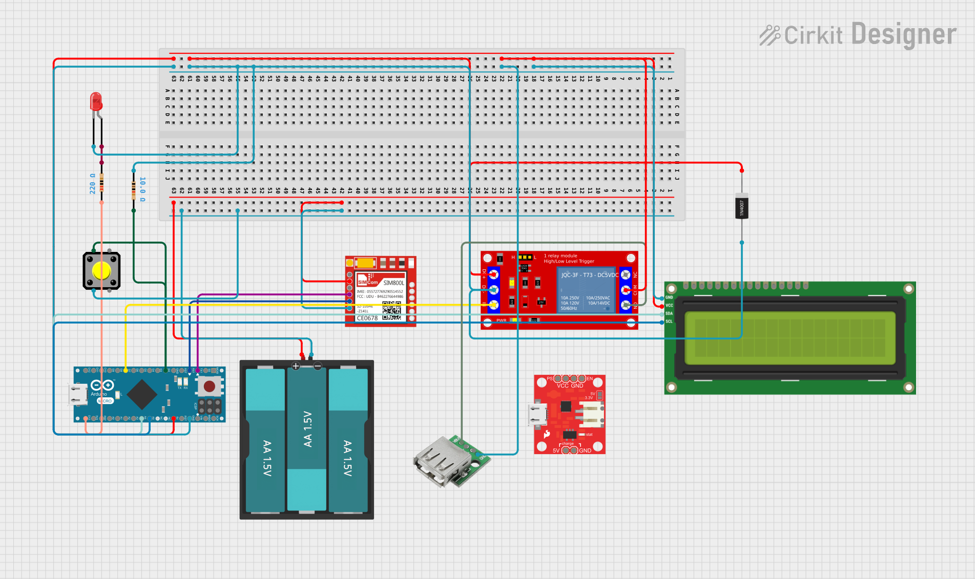
This circuit is designed to control a charging system using an Arduino Micro microcontroller. It features a GSM module (Sim800l) for communication, a relay module for controlling power to a charging device, an I2C LCD screen for displaying information, and various other components such as resistors, an LED, a pushbutton, and a diode for protection. The system operates by receiving payments via SMS, which then adds balance to the system, allowing for a certain amount of charging time.
Component List
Microcontroller
- Arduino Micro (Rev3): A microcontroller board based on the ATmega32u4, with digital and analog I/O pins, and built-in USB communication.
Communication Module
- Sim800l: A GSM/GPRS module that allows the circuit to send and receive SMS messages for payment confirmation and system status updates.
Power Control
- 1 Channel 5V Relay Module: An electromechanical switch used to control the power to the charging device.
Power Sources
- Battery AAx3 4.5V: Provides power to the Sim800l GSM module.
- USB Female: Used to provide 5V power input to the circuit.
Display
- I2C LCD 16x2 Screen: A 16x2 character LCD display with an I2C interface for showing balance and other status messages.
Indicators
- LED: Two Pin (red): An indicator light that shows the status of the charging system.
Protection
- 1N4007 Rectifier Diode: Used to prevent reverse current flow that could damage the circuit.
User Input
- Pushbutton: Allows the user to interact with the circuit, possibly to initiate a function or reset the system.
Resistors
- Resistor (10 Ohms): Used for current limiting or other purposes in the circuit.
- Resistor (220 Ohms): Typically used to limit current to an LED.
Power Management
- Power Cell - LiPo Charger/Booster: Manages the charging and boosting of a LiPo battery for the circuit.
Wiring Details
Arduino Micro (Rev3)
- 5V: Connected to the 5V pins of the I2C LCD screen, relay module, and diode.
- GND: Connected to the ground pins of the I2C LCD screen, USB female, resistor (10 Ohms), relay module, and diode.
- D1/TX: Connected to the RXD pin of the Sim800l.
- D0/RX: Connected to the TXD pin of the Sim800l.
- D2/SDA: Connected to one side of the resistor (10 Ohms) and the pushbutton.
- D7: Connected to the IN pin of the relay module.
- A5: Connected to the SCL pin of the I2C LCD screen.
- A4: Connected to the SDA pin of the I2C LCD screen.
- D13 PWM: Connected to one side of the resistor (220 Ohms).
Sim800l
- VCC: Connected to the VCC pin of the Battery AAx3 4.5V.
- GND: Connected to the GND pin of the Battery AAx3 4.5V and the pushbutton.
- RXD: Connected to the D1/TX pin of the Arduino Micro.
- TXD: Connected to the D0/RX pin of the Arduino Micro.
1 Channel 5V Relay Module
- VCC+: Connected to the 5V supply.
- VCC- (GND): Connected to the ground.
- IN: Connected to the D7 pin of the Arduino Micro.
- COM: Connected to the 5V supply.
- N.O.: Connected to the VCC pin of the USB Female.
Battery AAx3 4.5V
- VCC: Connected to the VCC pin of the Sim800l.
- GND: Connected to the GND pin of the Sim800l.
I2C LCD 16x2 Screen
- VCC (5V): Connected to the 5V supply.
- GND: Connected to the ground.
- SCL: Connected to the A5 pin of the Arduino Micro.
- SDA: Connected to the A4 pin of the Arduino Micro.
LED: Two Pin (red)
- cathode: Connected to the ground through a resistor (10 Ohms).
- anode: Connected to the D13 PWM pin of the Arduino Micro through a resistor (220 Ohms).
Pushbutton
- Pin 2: Connected to the ground.
- Pin 1: Connected to the D2/SDA pin of the Arduino Micro.
Resistors
- Resistor (10 Ohms): Connected between the ground and the cathode of the LED.
- Resistor (220 Ohms): Connected between the D13 PWM pin of the Arduino Micro and the anode of the LED.
USB Female
- VCC: Connected to the N.O. pin of the relay module.
- GND: Connected to the ground.
1N4007 Rectifier Diode
- Cathode: Connected to the 5V supply.
- Anode: Connected to the ground.
Documented Code
#include <Wire.h>
#include <LiquidCrystal_I2C.h>
#include <SoftwareSerial.h>

// Initialize the LCD
LiquidCrystal_I2C lcd(0x27, 16, 2);

// Set up the GSM Module
SoftwareSerial gsmSerial(1, 0); // RX, TX

// Pin Definitions
const int relayPin = 7;      // Pin connected to the relay module
const int buttonPin = 2;     // Pin connected to the button
const int ledPin = 13;       // Onboard LED for status indication

// Variables
int balance = 0;             // Prepaid balance (in seconds)
const int chargeRate = 1;    // Amount to deduct per second of charging

void setup() {
  // Initialize pins
  pinMode(relayPin, OUTPUT);
  pinMode(buttonPin, INPUT_PULLUP); // Using internal pull-up resistor
  pinMode(ledPin, OUTPUT);

  // Initialize the LCD
  lcd.begin(16, 2); // Corrected to include the number of columns and rows
  lcd.backlight();
  lcd.print("UPI Charging");

  // Initialize GSM Module
  gsmSerial.begin(9600);
  sendSMS("System Ready for UPI Payment!");

  // Initial state
  digitalWrite(relayPin, LOW); // Ensure relay is off
  digitalWrite(ledPin, LOW);   // LED off initially
}

void loop() {
  // Check if an SMS is received
  if (gsmSerial.available()) {
    String sms = gsmSerial.readString();
    if (sms.indexOf("PAYMENT") >= 0) {
      // Simulate UPI payment received
      balance += 60; // Add 60 seconds of charge time
      sendSMS("Payment Received. Balance Added: 60s");
    }
  }

  // Display current balance
  lcd.setCursor(0, 1);
  lcd.print("Balance: ");
  lcd.print(balance);
  lcd.print("s   "); // Print seconds

  // If balance is greater than 0, enable charging
  if (balance > 0) {
    digitalWrite(relayPin, HIGH); // Turn on the relay (charging enabled)
    digitalWrite(ledPin, HIGH);   // Turn on the LED
    delay(1000);                  // 1 second delay

    // Deduct balance
    balance -= chargeRate; // Deduct 1 second of charge time
  } else {
    // No balance, disable charging
    digitalWrite(relayPin, LOW);  // Turn off the relay
    digitalWrite(ledPin, LOW);    // Turn off the LED
  }
}

void sendSMS(String message) {
  gsmSerial.println("AT+CMGF=1"); // Set SMS mode to text
  delay(100);
  gsmSerial.println("AT+CMGS=\"+1234567890\""); // Replace with your phone number
  delay(100);
  gsmSerial.println(message);
  delay(100);
  gsmSerial.write(26); // ASCII code for CTRL+Z to send the message
  delay(1000);
}
This code is responsible for controlling the charging system. It initializes the LCD and GSM module, sets up the pins, and enters a loop where it checks for incoming SMS messages indicating payment. Upon receiving a payment, it adds balance and enables the relay to allow charging. The balance is displayed on the LCD and is decremented every second until it runs out, at which point the relay and LED are turned off. The sendSMS function is used to send SMS messages to notify the user of system status.