
Arduino-Controlled Soundwave Generator with IR Sensor Activation and LCD Feedback
View and Edit Project In Cirkit Designer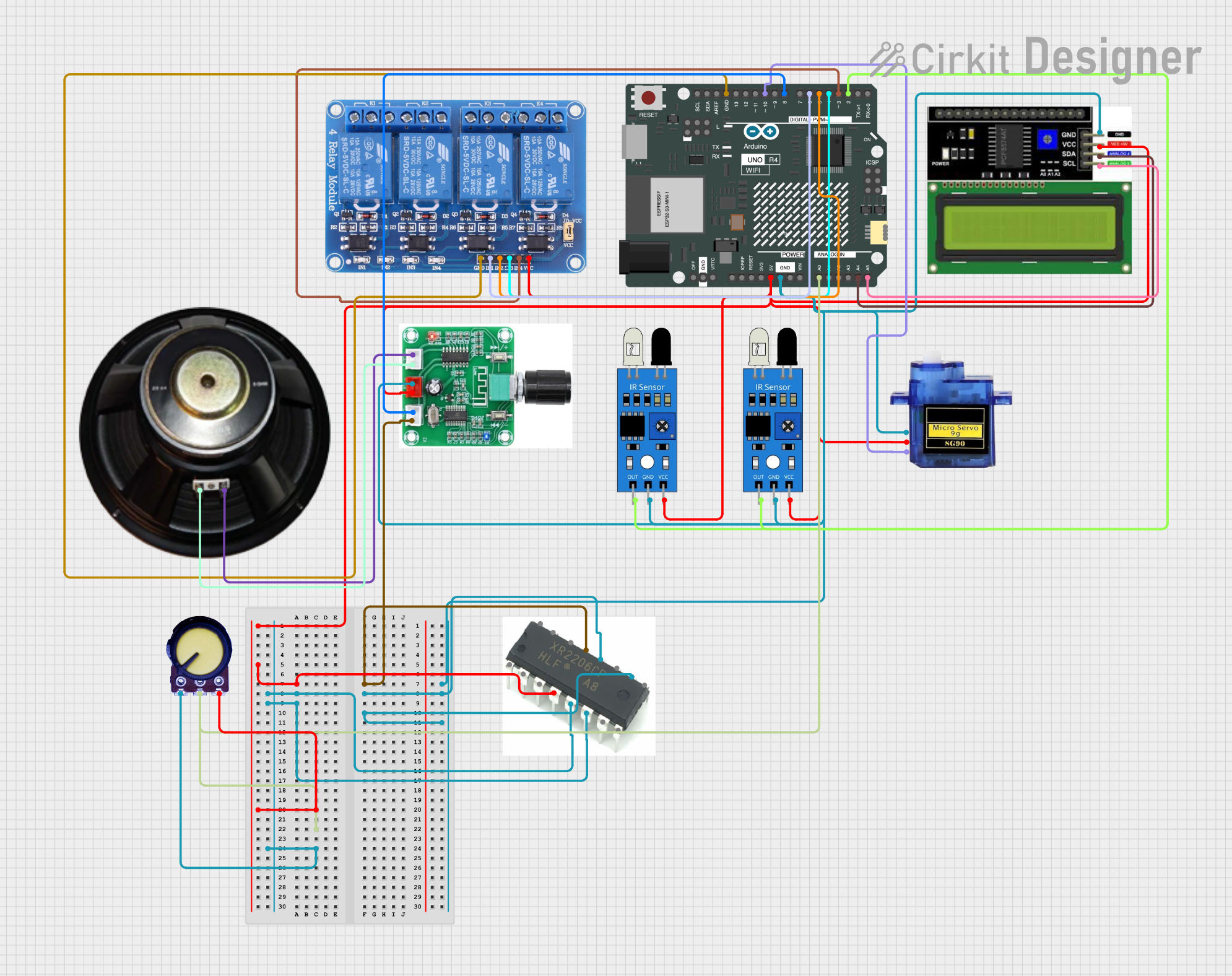
Circuit Documentation
Summary
This circuit is designed to generate a soundwave frequency using an XR2206 function generator, which is then output through a speaker. The frequency of the soundwave can be adjusted using a potentiometer. The circuit also includes a 4-channel relay module that is controlled by an Arduino UNO R4 WiFi microcontroller, which also reads input from IR sensors to trigger actions. Additionally, the circuit interfaces with an LCD display via I2C to show relevant information such as frequency and IR sensor status. A micro servo is included and is controlled based on the IR sensor input.
Component List
Relay 4 Channel 5v
- A 4-channel relay module that can control up to four separate high-power devices.
LCD I2C Display
- An LCD display that communicates with the microcontroller via the I2C protocol.
IR Sensor
- Two IR sensors that detect the presence of an object or movement.
Micro Servo 9G
- A small servo motor that can be positioned at various angles.
Arduino UNO R4 WiFi
- A microcontroller board based on the ATmega328, with built-in WiFi capability.
PAM8403
- A small digital amplifier used to amplify audio signals for the speaker.
XR2206 HLF 224A8
- A function generator IC capable of producing various waveforms at adjustable frequencies.
Speaker
- An audio output device that converts electrical signals into sound.
Potentiometer
- A variable resistor that can be used to adjust the frequency of the function generator.
Wiring Details
Relay 4 Channel 5v
- GND: Connected to the common ground.
- IN1 - IN4: Controlled by digital pins D6, D5, D4, and D3 on the Arduino UNO R4 WiFi.
- VCC: Connected to the 5V power supply.
LCD I2C Display
- GND: Connected to the common ground.
- VCC: Connected to the 5V power supply.
- SDA: Connected to analog pin A4 on the Arduino UNO R4 WiFi.
- SCL: Connected to analog pin A5 on the Arduino UNO R4 WiFi.
IR Sensor
- out: One sensor's output connected to digital pin D2 on the Arduino UNO R4 WiFi.
- gnd: Connected to the common ground.
- vcc: Connected to the 5V power supply.
Micro Servo 9G
- GND: Connected to the common ground.
- +5V: Connected to the 5V power supply.
- PWM: Controlled by digital pin D10 on the Arduino UNO R4 WiFi.
Arduino UNO R4 WiFi
- GND: Common ground for the circuit.
- 5V: Provides power to the components requiring 5V.
PAM8403
- -: Connected to the common ground and the negative terminal of the speaker.
- +: Connected to the positive terminal of the speaker and receives input from the XR2206 function generator.
XR2206 HLF 224A8
- VCC: Connected to the 5V power supply.
- GND: Connected to the common ground.
- WAVEA1: Connected to the positive input of the PAM8403 amplifier.
Speaker
- +: Connected to the positive output of the PAM8403 amplifier.
- -: Connected to the negative output of the PAM8403 amplifier.
Potentiometer
- GND: Connected to the common ground.
- Output: Connected to analog pin A0 on the Arduino UNO R4 WiFi.
- VCC: Connected to the 5V power supply.
Documented Code
/*
 * This Arduino sketch generates a soundwave frequency using the XR2206
 * function generator and outputs it through a speaker. The frequency
 * can be adjusted using a potentiometer. The sketch also controls a
 * relay module and reads input from IR sensors to trigger actions.
 * Additionally, it interfaces with an LCD display via I2C to show
 * relevant information.
 */

#include <Wire.h>
#include <LiquidCrystal_I2C.h>
#include <Servo.h>

// Pin definitions
#define RELAY_IN1 6
#define RELAY_IN2 5
#define RELAY_IN3 4
#define RELAY_IN4 3
#define IR_SENSOR_PIN 2
#define SERVO_PIN 10
#define POT_PIN A0
#define LCD_ADDR 0x27
#define LCD_COLS 16
#define LCD_ROWS 2
#define SPEAKER_PIN 8

// Initialize LCD
LiquidCrystal_I2C lcd(LCD_ADDR, LCD_COLS, LCD_ROWS);

// Initialize Servo
Servo myServo;

void setup() {
  // Initialize serial communication
  Serial.begin(9600);

  // Initialize LCD
  lcd.begin(16, 2);
  lcd.backlight();

  // Initialize relay pins
  pinMode(RELAY_IN1, OUTPUT);
  pinMode(RELAY_IN2, OUTPUT);
  pinMode(RELAY_IN3, OUTPUT);
  pinMode(RELAY_IN4, OUTPUT);

  // Initialize IR sensor pin
  pinMode(IR_SENSOR_PIN, INPUT);

  // Initialize servo
  myServo.attach(SERVO_PIN);

  // Initialize potentiometer pin
  pinMode(POT_PIN, INPUT);

  // Initialize speaker pin
  pinMode(SPEAKER_PIN, OUTPUT);
}

void loop() {
  // Read potentiometer value
  int potValue = analogRead(POT_PIN);

  // Map potentiometer value to frequency range
  int frequency = map(potValue, 0, 1023, 20, 20000);

  // Output frequency to serial monitor
  Serial.print("Frequency: ");
  Serial.println(frequency);

  // Display frequency on LCD
  lcd.setCursor(0, 0);
  lcd.print("Freq: ");
  lcd.print(frequency);
  lcd.print(" Hz");

  // Generate soundwave frequency
  tone(SPEAKER_PIN, frequency);

  // Read IR sensor value
  int irValue = digitalRead(IR_SENSOR_PIN);

  // Display IR sensor status on LCD
  lcd.setCursor(0, 1);
  lcd.print("IR: ");
  lcd.print(irValue == HIGH ? "Detected" : "Not Detected");

  // Control relay based on IR sensor value
  digitalWrite(RELAY_IN1, irValue);
  digitalWrite(RELAY_IN2, irValue);
  digitalWrite(RELAY_IN3, irValue);
  digitalWrite(RELAY_IN4, irValue);

  // Control servo based on IR sensor value
  if (irValue == HIGH) {
    myServo.write(90); // Move servo to 90 degrees
  } else {
    myServo.write(0); // Move servo to 0 degrees
  }

  // Delay for stability
  delay(100);
}
This code is responsible for controlling the various components of the circuit. It reads the potentiometer to determine the frequency of the soundwave, controls the relay and servo based on the IR sensor input, and displays information on the LCD screen.