Arduino UNO Based Security Keypad with Access Indicator LEDs and Buzzer Feedback
Circuit Documentation
Summary
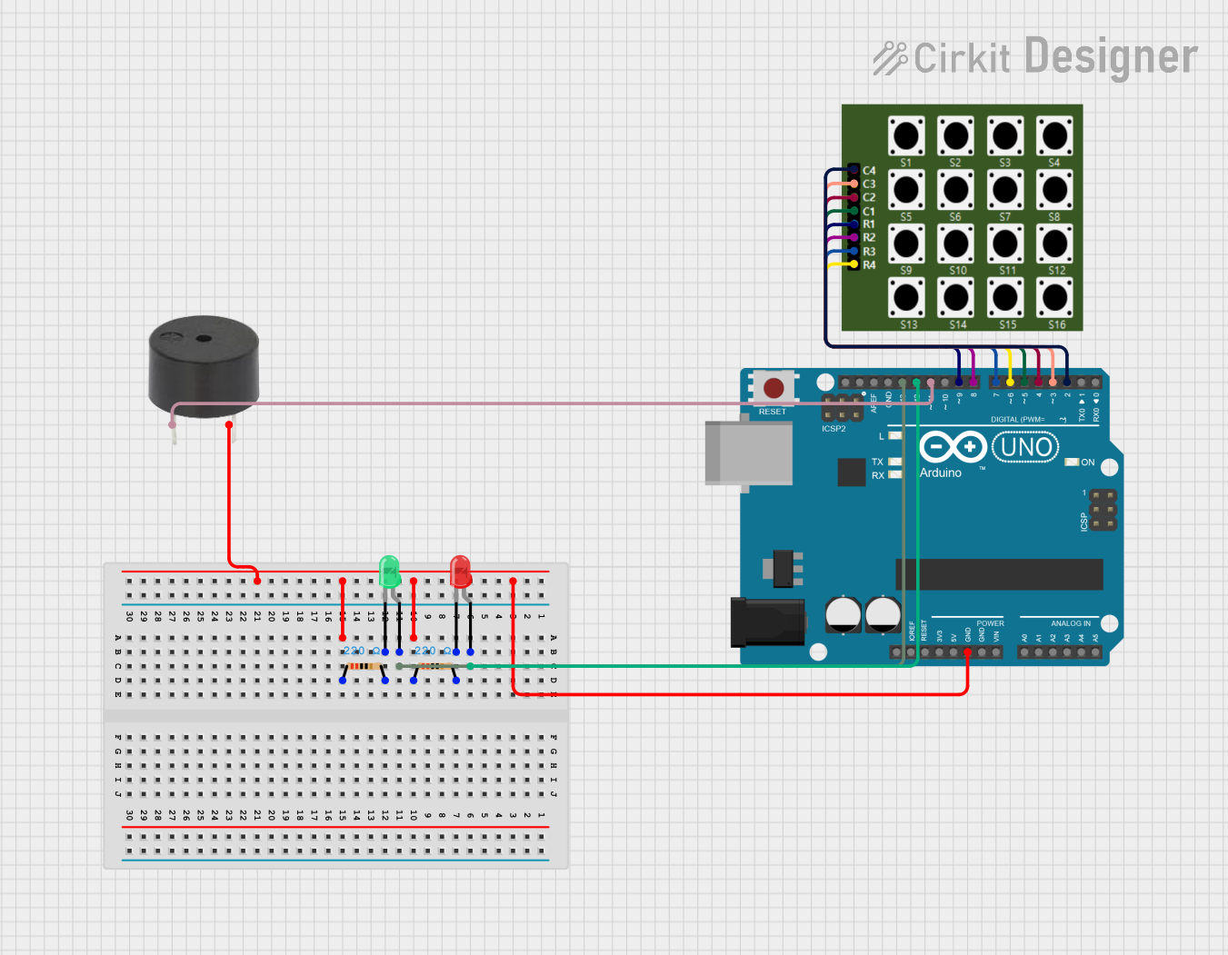
This circuit is designed to create a keypad-based access control system using an Arduino UNO microcontroller. The system allows users to input a passcode using a 4x4 keypad. If the correct passcode is entered, a green LED lights up indicating access granted, and a buzzer sounds a single long beep. If an incorrect passcode is entered, a red LED lights up indicating access denied, and the buzzer emits three short beeps. The circuit includes resistors to limit current to the LEDs and a buzzer for audible feedback.
Component List
Arduino UNO
- Microcontroller board based on the ATmega328P
- It has 14 digital input/output pins, 6 analog inputs, a 16 MHz quartz crystal, a USB connection, a power jack, an ICSP header, and a reset button.
Resistor (220 Ohms)
- Two resistors with a resistance of 220 Ohms each
- Used to limit the current flowing through the LEDs to prevent damage
LED: Two Pin (red)
- A red LED with an anode and cathode pin
- Lights up red when access is denied
LED: Two Pin (green)
- A green LED with an anode and cathode pin
- Lights up green when access is granted
4×4 Keypad
- A matrix keypad with 16 buttons arranged in 4 rows and 4 columns
- Used for passcode input
Buzzer
- An electronic buzzer with a pin for signal input and a ground pin
- Provides audible feedback for passcode entry results
Wiring Details
Arduino UNO
- GND connected to the ground pins of both resistors and the buzzer
- Digital pins D2 to D9 connected to the 4x4 Keypad (D2-D5 for columns C1-C4, D6-D9 for rows R1-R4)
- Digital pin D11 connected to the buzzer signal pin
- Digital pin D12 connected to the anode of the red LED
- Digital pin D13 connected to the anode of the green LED
Resistor (220 Ohms)
- One side connected to the ground (GND) of the Arduino UNO
- The other side connected to the cathode of the respective LED (red or green)
LED: Two Pin (red)
- Anode connected to Arduino UNO digital pin D12
- Cathode connected to one of the 220 Ohm resistors
LED: Two Pin (green)
- Anode connected to Arduino UNO digital pin D13
- Cathode connected to the other 220 Ohm resistor
4×4 Keypad
- Rows R1 to R4 connected to Arduino UNO digital pins D9 to D6 respectively
- Columns C1 to C4 connected to Arduino UNO digital pins D5 to D2 respectively
Buzzer
- Signal pin connected to Arduino UNO digital pin D11
- Ground pin connected to Arduino UNO GND
Documented Code
#include <Keypad.h>

const byte ROWS = 4;
const byte COLS = 4;

char hexaKeys[ROWS][COLS] = {
  {'1', '2', '3', 'A'},
  {'4', '5', '6', 'B'},
  {'7', '8', '9', 'C'},
  {'*', '0', '#', 'D'}
};

byte rowPins[ROWS] = {9, 8, 7, 6};
byte colPins[COLS] = {5, 4, 3, 2};

Keypad customKeypad = Keypad(makeKeymap(hexaKeys), rowPins, colPins, ROWS, COLS);

// Define the correct passcode
String correctPasscode = "1234";
String enteredPasscode = "";

// Define LED and buzzer pins
const int greenLEDPin = 13;  // Green LED for Access Granted
const int redLEDPin = 12;    // Red LED for Access Denied
const int buzzerPin = 11;    // Buzzer pin for sound feedback

void setup(){
  Serial.begin(9600);

  // Set LED and buzzer pins as output
  pinMode(greenLEDPin, OUTPUT);
  pinMode(redLEDPin, OUTPUT);
  pinMode(buzzerPin, OUTPUT);

  // Turn off both LEDs and the buzzer at the start
  digitalWrite(greenLEDPin, LOW);
  digitalWrite(redLEDPin, LOW);
  digitalWrite(buzzerPin, LOW);
}

void loop(){
  char customKey = customKeypad.getKey();

  if (customKey) {
    // Print the entered key
    Serial.print(customKey);

    // Add key to entered passcode (except if it's '*' or '#')
    if (customKey != '*' && customKey != '#') {
      enteredPasscode += customKey;
    }

    // If '#' is pressed, it means user is done entering the passcode (Enter button)
    if (customKey == '#') {
      Serial.print("\nPasscode Entered: ");
      Serial.println(enteredPasscode);

      // Check if the entered passcode matches the correct one
      if (enteredPasscode == correctPasscode) {
        Serial.println("Access Granted!");
        digitalWrite(greenLEDPin, HIGH);  // Turn on Green LED (Access granted)
        digitalWrite(redLEDPin, LOW);     // Ensure Red LED is off

        // Buzzer for correct passcode: Single long beep
        tone(buzzerPin, 1000);   // 1000 Hz frequency
        delay(500);              // 500 ms beep
        noTone(buzzerPin);       // Stop the buzzer

      } else {
        Serial.println("Access Denied!");
        digitalWrite(redLEDPin, HIGH);   // Turn on Red LED (Access denied)
        digitalWrite(greenLEDPin, LOW);  // Ensure Green LED is off

        // Buzzer for incorrect passcode: 3 short beeps
        for (int i = 0; i < 3; i++) {
          tone(buzzerPin, 1000);   // 1000 Hz frequency
          delay(200);              // 200 ms beep
          noTone(buzzerPin);       // Stop the buzzer
          delay(100);              // Small pause between beeps
        }
      }
      enteredPasscode = "";  // Clear the entered passcode after checking
    }

    // If '*' is pressed, it clears the current entry (Reset button)
    if (customKey == '*') {
      enteredPasscode = "";
      Serial.println("\nPasscode Cleared!");

      // Turn off both LEDs and the buzzer when passcode is cleared
      digitalWrite(greenLEDPin, LOW);
      digitalWrite(redLEDPin, LOW);
      noTone(buzzerPin);
    }
  }
}
This code is designed to run on an Arduino UNO and interfaces with a 4x4 keypad, a red LED, a green LED, and a buzzer. It sets up the keypad and defines the pins for the LEDs and buzzer. The main loop waits for a keypress, builds the entered passcode, and checks it against a predefined correct passcode. Depending on whether the passcode is correct or not, it provides visual and audible feedback.