Solar-Powered LED Bulb with Pushbutton Control and Capacitive Smoothing
Circuit Documentation
Summary
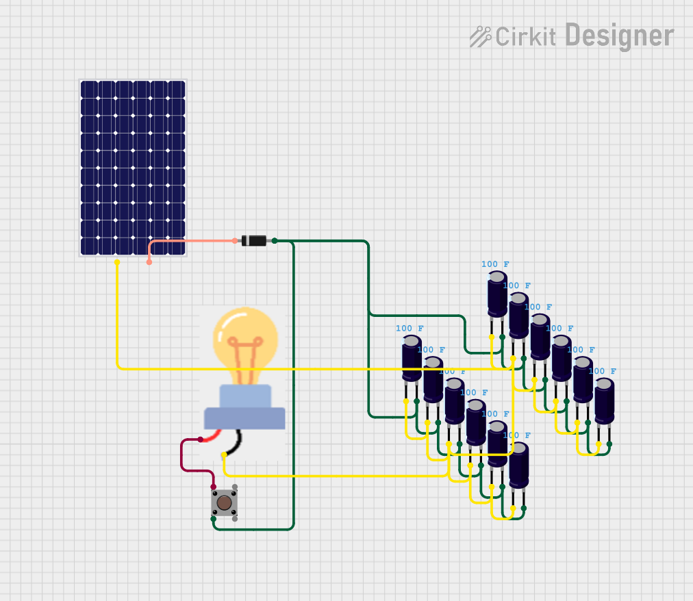
The circuit in question appears to be a simple power supply and load circuit, which includes a solar panel as the power source, a series of electrolytic capacitors for energy storage or filtering, a diode for current direction control, a pushbutton as a control interface, and a bulb as a load. The solar panel charges the capacitors, and the diode ensures that the current flows in one direction, preventing backflow to the solar panel. The pushbutton likely controls the power flow to the bulb. Since there is no microcontroller code provided, the circuit functions without programmable control logic.
Component List
Electrolytic Capacitors
- Description: Electrolytic capacitors are used for energy storage and can provide filtering in power supply circuits.
- Properties: Each capacitor has a capacitance of 100 Farads.
Diode
- Description: A diode allows current to flow in only one direction, which is useful for protecting circuits from reverse current.
- Properties: Standard diode with an anode and cathode.
Bulb
- Description: The bulb serves as the load in the circuit and will illuminate when power is supplied.
- Properties: Standard electrical bulb with power and ground connections.
Pushbutton
- Description: A pushbutton is a momentary switch that can control the flow of electricity in a circuit.
- Properties: It has two pairs of pins, with each pair connected internally.
Solar Panel
- Description: The solar panel is the power source in this circuit, converting light into electrical energy.
- Properties: It has positive and negative terminals for power output.
Wiring Details
Electrolytic Capacitors
- Connections:
- All negative pins (-) are connected to the ground (GND) of the bulb and the positive (+) terminal of the solar panel.
- All positive pins (+) are connected to the anode of the diode and the second pin (Pin 2) of the pushbutton.
Diode
- Connections:
- Anode connected to the positive pins (+) of all electrolytic capacitors.
- Cathode connected to the negative (-) terminal of the solar panel.
Bulb
- Connections:
- GND connected to the negative pins (-) of all electrolytic capacitors.
- Power connected to the first pin (Pin 1) of the pushbutton.
Pushbutton
- Connections:
- Pin 1 (in) connected to the power pin of the bulb.
- Pin 2 (in) connected to the positive pins (+) of all electrolytic capacitors.
Solar Panel
- Connections:
- Positive (+) terminal connected to the negative pins (-) of all electrolytic capacitors.
- Negative (-) terminal connected to the cathode of the diode.
Documented Code
No code has been provided for this circuit. The circuit operates purely on electrical connections without any programmable logic controllers or microcontrollers.
This documentation provides an overview of the circuit's components, their properties, and how they are wired together. The absence of code indicates that the circuit's functionality is not controlled by any software, and its behavior is determined solely by the hardware configuration and the physical properties of the components used.