
Arduino UNO-Based Battery-Powered Water Level Monitoring System with Siren Alert
View and Edit Project In Cirkit Designer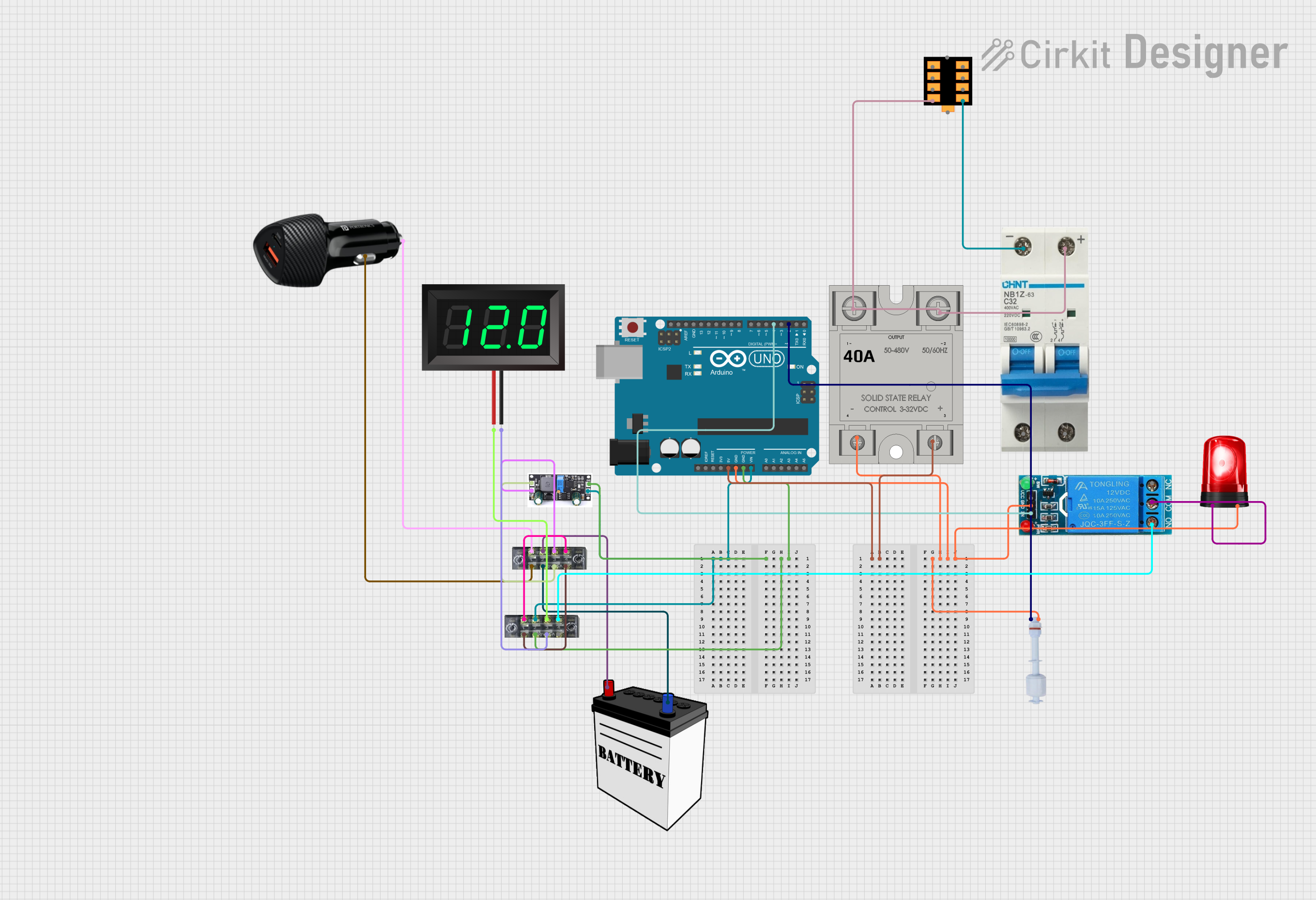
Circuit Documentation
Summary
This document provides a detailed overview of a circuit that includes various components such as an Arduino UNO, relays, a solid-state relay, a float switch, a siren, a power distribution board, a 12V battery, a charge controller, a 7-segment panel voltmeter, and a 12V battery charger. The circuit is designed to control and monitor various electrical devices and sensors.
Component List
SSR-40A
- Description: Solid State Relay
- Pins: -, +, Lin, Lout
12V SINGLE CHANNEL RELAY
- Description: Single Channel Relay Module
- Pins: NC, COM, NO, IN, GND, VCC
Circuit Breaker
- Description: Circuit Breaker
- Pins: -, +
Power Distribution Board
- Description: Power Distribution Board
- Pins: Power OUT0, Power OUT1, Power OUT2, Power OUT3, Power OUT4, Power OUT5, Power OUT6, Power OUT7, Power OUT8, Power IN
Float Switch
- Description: Float Switch
- Pins: GND, Digital Pin
Siren
- Description: Siren
- Pins: Positive, Ground
12V Battery
- Description: 12V Battery
- Pins: VCC, GND
Arduino UNO
- Description: Microcontroller Board
- Pins: UNUSED, IOREF, Reset, 3.3V, 5V, GND, Vin, A0, A1, A2, A3, A4, A5, SCL, SDA, AREF, D13, D12, D11, D10, D9, D8, D7, D6, D5, D4, D3, D2, D1, D0
7-Segment Panel Voltmeter
- Description: 7-Segment Panel Voltmeter
- Pins: V+, V-
Charge Controller
- Description: Charge Controller
- Pins: GND, BAT, Vin
Terminal Block
- Description: Terminal Block
- Pins: 1, 2, 3, 4, 5, 6, 7, 8
12V Battery Charger
- Description: 12V Battery Charger
- Pins: -ve, +ve
Wiring Details
SSR-40A
- + connected to Arduino UNO 5V
- - connected to Float Switch GND, Arduino UNO GND, Siren Ground, 12V SINGLE CHANNEL RELAY GND
- Lin connected to Power Distribution Board Power OUT3, Circuit Breaker +
- Lout connected to Power Distribution Board Power OUT3, Circuit Breaker +
12V SINGLE CHANNEL RELAY
- GND connected to Float Switch GND, Arduino UNO GND, SSR-40A -, Siren Ground
- COM connected to Siren Positive
- NO connected to Terminal Block 7
- IN connected to Arduino UNO D4
Circuit Breaker
- + connected to Power Distribution Board Power OUT3, SSR-40A Lin
- - connected to Power Distribution Board Power OUT7
Power Distribution Board
- Power OUT3 connected to SSR-40A Lin, SSR-40A Lout, Circuit Breaker +
- Power OUT7 connected to Circuit Breaker -
Float Switch
- GND connected to Arduino UNO GND, SSR-40A -, Siren Ground, 12V SINGLE CHANNEL RELAY GND
- Digital Pin connected to Arduino UNO D2
Siren
- Ground connected to Float Switch GND, Arduino UNO GND, SSR-40A -, 12V SINGLE CHANNEL RELAY GND
- Positive connected to 12V SINGLE CHANNEL RELAY COM
12V Battery
- VCC connected to Terminal Block 3
- GND connected to Terminal Block 4
Arduino UNO
- 5V connected to SSR-40A +
- GND connected to Float Switch GND, SSR-40A -, Siren Ground, 12V SINGLE CHANNEL RELAY GND
- Vin connected to Charge Controller Vin, Terminal Block 3
- D2 connected to Float Switch Digital Pin
- D4 connected to 12V SINGLE CHANNEL RELAY IN
7-Segment Panel Voltmeter
- V+ connected to Terminal Block 5
- V- connected to Terminal Block 6
Charge Controller
- GND connected to Terminal Block 6
- BAT connected to Terminal Block 5
- Vin connected to Arduino UNO Vin, Terminal Block 3
Terminal Block
- 1 connected to 12V Battery Charger +ve, Terminal Block 7
- 2 connected to 12V Battery Charger -ve, Terminal Block 8
- 3 connected to 12V Battery VCC, Charge Controller Vin, Arduino UNO Vin
- 4 connected to 12V Battery GND
- 5 connected to Charge Controller BAT, 7-Segment Panel Voltmeter V+
- 6 connected to Charge Controller GND, 7-Segment Panel Voltmeter V-
- 7 connected to 12V SINGLE CHANNEL RELAY NO, Terminal Block 1
- 8 connected to Terminal Block 2
12V Battery Charger
- +ve connected to Terminal Block 1
- -ve connected to Terminal Block 2
Documented Code
Arduino UNO Code (sketch.ino)
void setup() {
  // put your setup code here, to run once:

}

void loop() {
  // put your main code here, to run repeatedly:

}
Additional Documentation (documentation.txt)