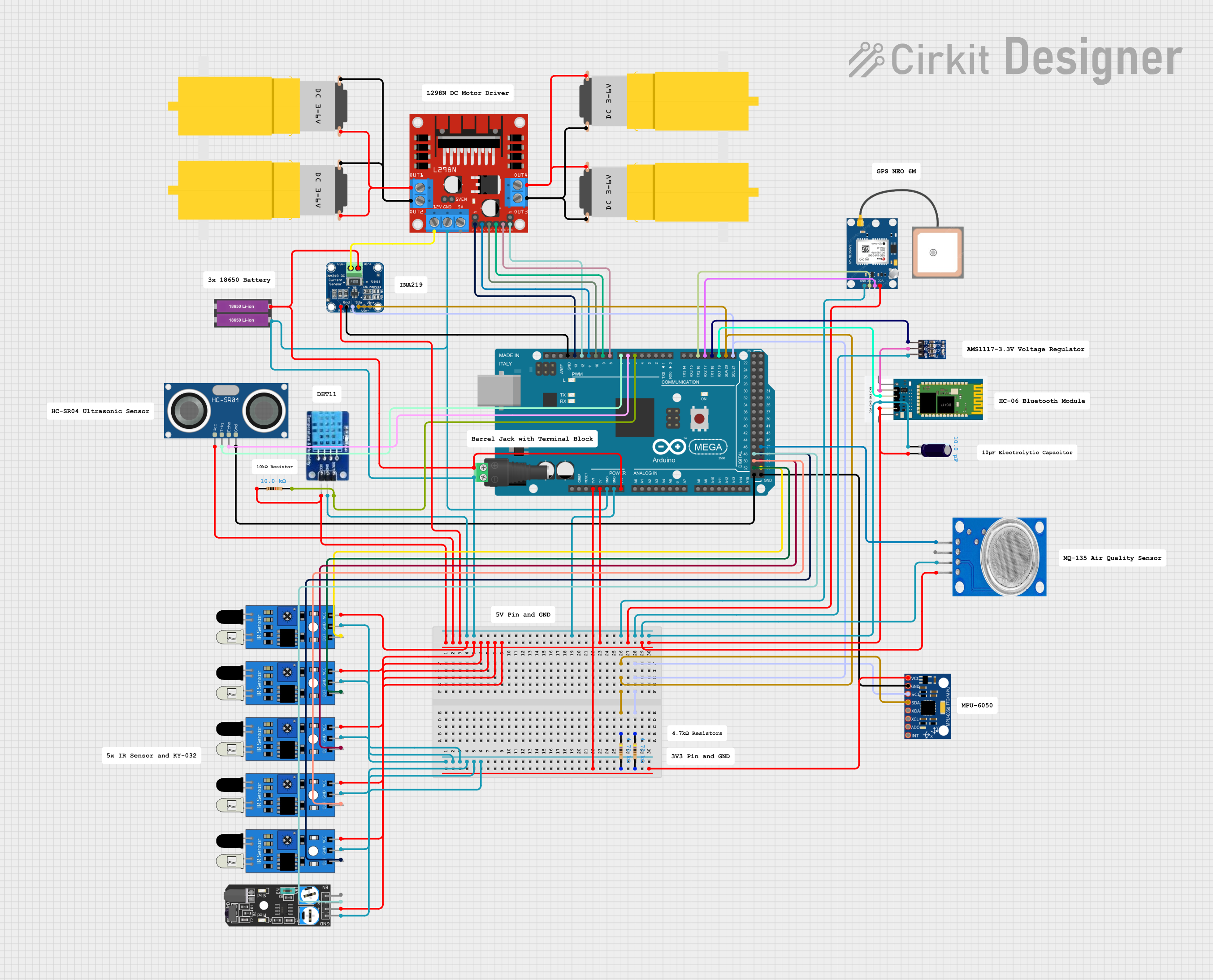
Arduino Mega 2560-Based Robotic Control System with Sensor Integration and Bluetooth Connectivity

Circuit Documentation
Summary
This document provides a detailed overview of a circuit designed to interface various sensors and actuators with an Arduino Mega 2560 microcontroller. The circuit includes motor drivers to control DC motors, a range of sensors for distance measurement, motion tracking, and environmental sensing, as well as communication modules for GPS and Bluetooth connectivity. Power management components ensure stable operation, and the microcontroller is programmed to coordinate the interactions between these components.
Component List
Microcontroller
- Arduino Mega 2560: A microcontroller board based on the ATmega2560, with a large number of IO pins, including digital, analog, and PWM, as well as I2C, SPI, and UART communication capabilities.
Sensors
- HC-SR04 Ultrasonic Sensor: Measures distance by emitting ultrasonic waves and measuring the time taken for the echo to return.
- MPU-6050: A motion tracking device with a 3-axis gyroscope and a 3-axis accelerometer.
- DHT11: A sensor for measuring temperature and humidity.
- GPS NEO 6M: A GPS module for determining geographical location.
- HC-06: A Bluetooth module for wireless communication.
- INA219: A current sensor for monitoring voltage and power consumption of the motors.
- MQ135: A gas sensor for detecting a wide range of gases, including NH3, NOx, alcohol, benzene, smoke, and CO2.
- KY-032 Infrared Obstacle Avoidance Sensor Module: An infrared sensor for detecting obstacles.
- IR Sensors: Used for object detection and distance measurement.
Actuators
- Motor amarillo motorreductor hobby: DC motors used for driving mechanisms such as wheels or gears.
- L298N DC Motor Driver: A motor driver module capable of driving two DC motors.
Power Management
- 18650 Li-ion Battery x 2: Provides power to the circuit.
- 2.1mm Barrel Jack with Terminal Block: Connects external power sources to the circuit.
- AMS1117 3.3: A voltage regulator that provides a stable 3.3V output.
- Electrolytic Capacitor: Stabilizes voltage and filters noise in the power supply.
Passive Components
- Resistors: Used for pull-up resistors on I2C lines and for current limiting.
- Electrolytic Capacitor: Used for power supply filtering.
Wiring Details
Arduino Mega 2560
- 5V: Powers the HC-SR04, DHT11, INA219, IR sensors, KY-032, and HC-06 modules.
- 3V3: Powers the MPU-6050 sensor.
- GND: Common ground for all components.
- VIN: Connected to the positive terminal of the Li-ion batteries.
- Digital Pins (D5-D13): Control signals for DHT11, HC-SR04, and L298N motor driver.
- I2C Pins (D20/SDA, D21/SCL): Communication with INA219 and MPU-6050 sensors.
- UART Pins (D18/TX1, D19/RX1, D16/TX2, D17/RX2): Communication with HC-06 Bluetooth module and GPS NEO 6M module.
- Digital Pins (D47-D53): Input from IR sensors and MQ135 gas sensor.
Sensors and Modules
- HC-SR04 Ultrasonic Sensor: TRIG and ECHO pins connected to D7 and D6 respectively.
- MPU-6050: SDA and SCL connected to corresponding I2C pins on Arduino with pull-up resistors.
- DHT11: DATA pin connected to D5 with a pull-up resistor.
- GPS NEO 6M: TX and RX connected to D16 and D17 (UART communication).
- HC-06 Bluetooth Module: RXD and TXD connected to D18 and D19 (UART communication).
- INA219 Current Sensor: SDA and SCL connected to I2C pins with pull-up resistors; VIN+ and VIN- connected to the motor driver and battery respectively.
- MQ135 Gas Sensor: Analog output connected to D47.
- KY-032 Infrared Obstacle Avoidance Sensor Module: Out pin connected to D48.
- IR Sensors: OUT pins connected to D49-D53.
Actuators
- L298N DC Motor Driver: IN1-IN4 control pins connected to D8-D11; ENA and ENB connected to D12 and D13 for PWM speed control; OUT1-OUT4 connected to the DC motors.
Power Management
- 18650 Li-ion Battery x 2: Provides power to VIN of Arduino and motor driver.
- 2.1mm Barrel Jack with Terminal Block: Connects the external power source to the circuit.
- AMS1117 3.3: VIN connected to Arduino's 5V, OUT to HC-06's VCC.
- Electrolytic Capacitor: Connected across the power supply lines for filtering.
Documented Code
Arduino Mega 2560 - sketch.ino
void setup() {
  // put your setup code here, to run once:

}

void loop() {
  // put your main code here, to run repeatedly:

}
This code is a template for the Arduino Mega 2560. The setup() function is called once when the microcontroller is powered on or reset. It is used to initialize the settings, such as pin modes or communication protocols. The loop() function is called repeatedly and contains the main logic of the program. It is here that the microcontroller will interact with the connected sensors and actuators based on the logic defined by the user.