Cirkit Designer
Your all-in-one circuit design IDE
Home /
Project Documentation
ESP32 and Arduino UNO Controlled CAN Bus Motor Driver with Limit Switch

Circuit Documentation
Summary
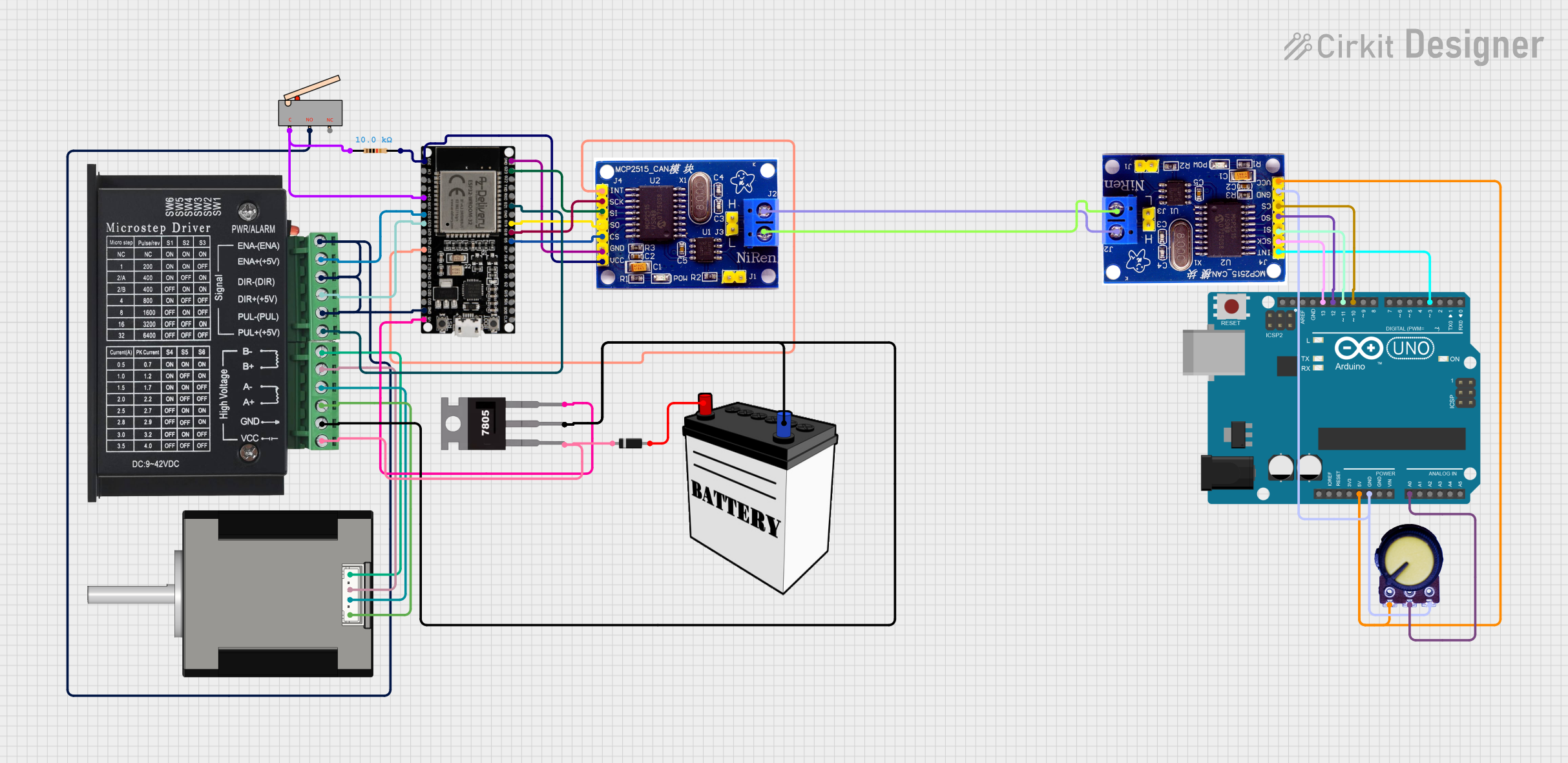
This document provides a detailed overview of a circuit that integrates various components including an ESP32 microcontroller, MCP2515 CAN controllers, a TB6600 stepper motor driver, a Nema 17 stepper motor, a 7805 voltage regulator, a potentiometer, a limit switch, a diode, a resistor, and a 12V battery. The circuit is designed to control a stepper motor and interface with a CAN bus network.
Component List
MCP2515
- Description: CAN controller
- Pins: INT, SCK, SI, SO, CS, GND, VCC, H, L
ESP32 38 PINS
- Description: Microcontroller
- Pins: GND, G23, G22, TXD, RXD, G21, G19, G18, G5, G17, G16, G4, G0, G2, G15, SDI, SD0, CLK, 3V3, EN, SP, SN, G34, G35, G32, 33, G25, G26, G27, G14, G12, G13, SD2, SD3, 5V
TB6600 Micro Stepping Motor Driver
- Description: Stepper motor driver
- Pins: ENA-, ENA+, DIR-, DIR+, PUL-, PUL+, B-, B+, A-, A+, GND, VCC
7805
- Description: Voltage regulator
- Pins: Vin, Gnd, Vout
Arduino UNO
- Description: Microcontroller
- Pins: UNUSED, IOREF, Reset, 3.3V, 5V, GND, Vin, A0, A1, A2, A3, A4, A5, SCL, SDA, AREF, D13, D12, D11, D10, D9, D8, D7, D6, D5, D4, D3, D2, D1, D0
Potentiometer
- Description: Variable resistor
- Pins: GND, Output, VCC
12V Battery
- Description: Power source
- Pins: VCC, GND
Diode
- Description: Diode
- Pins: cathode, anode
Resistor
- Description: Resistor
- Pins: pin1, pin2
- Properties: Resistance: 10000 Ohms
Nema 17 42-STH48
- Description: Stepper motor
- Pins: A2 (black), A1 Green, B2 Red, B1 Blue
Limit switch
- Description: Switch
- Pins: C, NO, NC
Wiring Details
MCP2515
- INT connected to ESP32 38 PINS G27
- SCK connected to ESP32 38 PINS G18
- SI connected to ESP32 38 PINS G23
- SO connected to ESP32 38 PINS G19
- CS connected to ESP32 38 PINS G5
- GND connected to ESP32 38 PINS GND
- VCC connected to ESP32 38 PINS 3V3 and Resistor pin2
- H connected to MCP2515 H of another MCP2515
- L connected to MCP2515 L of another MCP2515
ESP32 38 PINS
- G21 connected to TB6600 Micro Stepping Motor Driver PUL+
- G34 connected to Limit switch C and Resistor pin1
- G32 connected to TB6600 Micro Stepping Motor Driver ENA+
- 33 connected to TB6600 Micro Stepping Motor Driver DIR+
- GND connected to TB6600 Micro Stepping Motor Driver ENA-, DIR-, PUL-, and Limit switch NO
- 5V connected to 7805 Vout
TB6600 Micro Stepping Motor Driver
- B- connected to Nema 17 42-STH48 B1 Blue
- B+ connected to Nema 17 42-STH48 B2 Red
- A- connected to Nema 17 42-STH48 A1 Green
- A+ connected to Nema 17 42-STH48 A2 (black)
- GND connected to 7805 Gnd and 12V Battery GND
- VCC connected to 7805 Vin and Diode cathode
7805
- Gnd connected to 12V Battery GND and TB6600 Micro Stepping Motor Driver GND
- Vin connected to Diode cathode and TB6600 Micro Stepping Motor Driver VCC
- Vout connected to ESP32 38 PINS 5V
Arduino UNO
- D3 connected to MCP2515 INT
- D13 connected to MCP2515 SCK
- D11 connected to MCP2515 SI
- D12 connected to MCP2515 SO
- D10 connected to MCP2515 CS
- GND connected to Potentiometer VCC and MCP2515 GND
- 5V connected to Potentiometer GND and MCP2515 VCC
- A0 connected to Potentiometer Output
Potentiometer
- VCC connected to Arduino UNO GND and MCP2515 GND
- GND connected to Arduino UNO 5V and MCP2515 VCC
- Output connected to Arduino UNO A0
Diode
- cathode connected to 7805 Vin and TB6600 Micro Stepping Motor Driver VCC
- anode connected to 12V Battery VCC
Resistor
- pin1 connected to ESP32 38 PINS G34 and Limit switch C
- pin2 connected to MCP2515 VCC and ESP32 38 PINS 3V3
Nema 17 42-STH48
- B1 Blue connected to TB6600 Micro Stepping Motor Driver B-
- B2 Red connected to TB6600 Micro Stepping Motor Driver B+
- A1 Green connected to TB6600 Micro Stepping Motor Driver A-
- A2 (black) connected to TB6600 Micro Stepping Motor Driver A+
Limit switch
- C connected to ESP32 38 PINS G34 and Resistor pin1
- NO connected to ESP32 38 PINS GND and TB6600 Micro Stepping Motor Driver ENA-, DIR-, PUL-
Documented Code
Arduino UNO Code
void setup() {
  // put your setup code here, to run once:

}

void loop() {
  // put your main code here, to run repeatedly:

}
This document provides a comprehensive overview of the circuit, including the components used, their connections, and the code for the microcontroller.