
Battery-Powered Light-Activated Relay Circuit with Photocell and Transistor
View and Edit Project In Cirkit Designer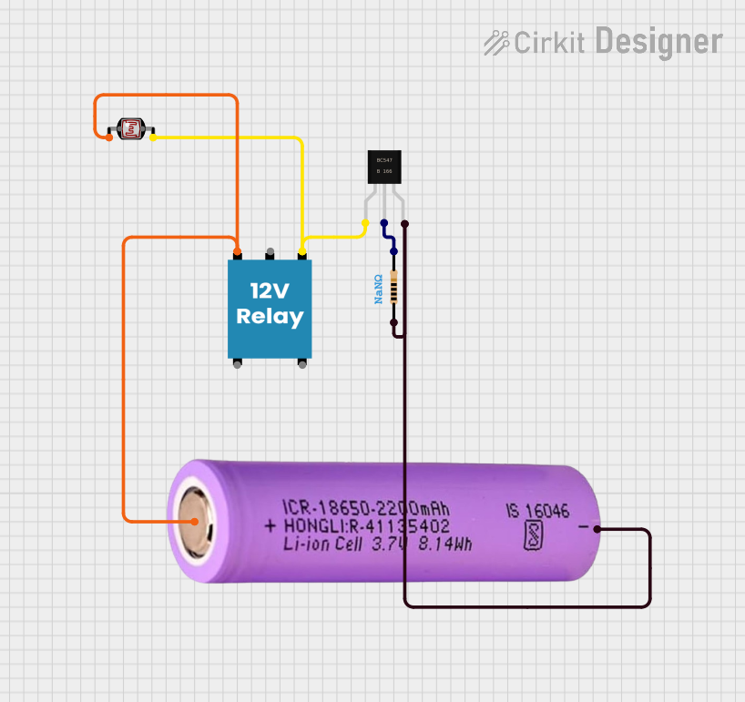
Circuit Documentation
Summary
This circuit is designed to control a 12V relay using a light-dependent resistor (LDR) and a BC547 transistor. The circuit is powered by a 18650 battery. The LDR senses the ambient light level, and based on this, the transistor switches the relay on or off.
Component List
Photocell (LDR)
- Description: A light-dependent resistor that changes its resistance based on the ambient light level.
- Pins: pin 0, pin 1
BC547 Transistor
- Description: A general-purpose NPN transistor used for switching applications.
- Pins: collector, base, emitter
Resistor
- Description: A passive electrical component that provides resistance to the flow of current.
- Pins: pin1, pin2
- Properties:
- Resistance: NaN Ohms
12V Relay
- Description: An electromechanical switch that is activated by an electrical signal.
- Pins: +, -, C, NC, NO
Battery 18650
- Description: A rechargeable lithium-ion battery.
- Pins: +, -
Wiring Details
Photocell (LDR)
pin 0 is connected to:
- 12V Relay pin +
- Battery 18650 pin +
pin 1 is connected to:
- BC547 Transistor collector
- 12V Relay pin -
BC547 Transistor
collector is connected to:
- Photocell (LDR) pin 1
- 12V Relay pin -
base is connected to:
- Resistor pin2
emitter is connected to:
- Resistor pin1
- Battery 18650 pin -
Resistor
pin1 is connected to:
- BC547 Transistor emitter
- Battery 18650 pin -
pin2 is connected to:
- BC547 Transistor base
12V Relay
+ is connected to:
- Photocell (LDR) pin 0
- Battery 18650 pin +
- is connected to:
- Photocell (LDR) pin 1
- BC547 Transistor collector
Battery 18650
+ is connected to:
- Photocell (LDR) pin 0
- 12V Relay pin +
- is connected to:
- Resistor pin1
- BC547 Transistor emitter
Code
There is no microcontroller code associated with this circuit.