Arduino UNO Controlled Load Cell Measurement System with OLED Display and Solenoid Valve Actuation
Circuit Documentation
Summary of the Circuit
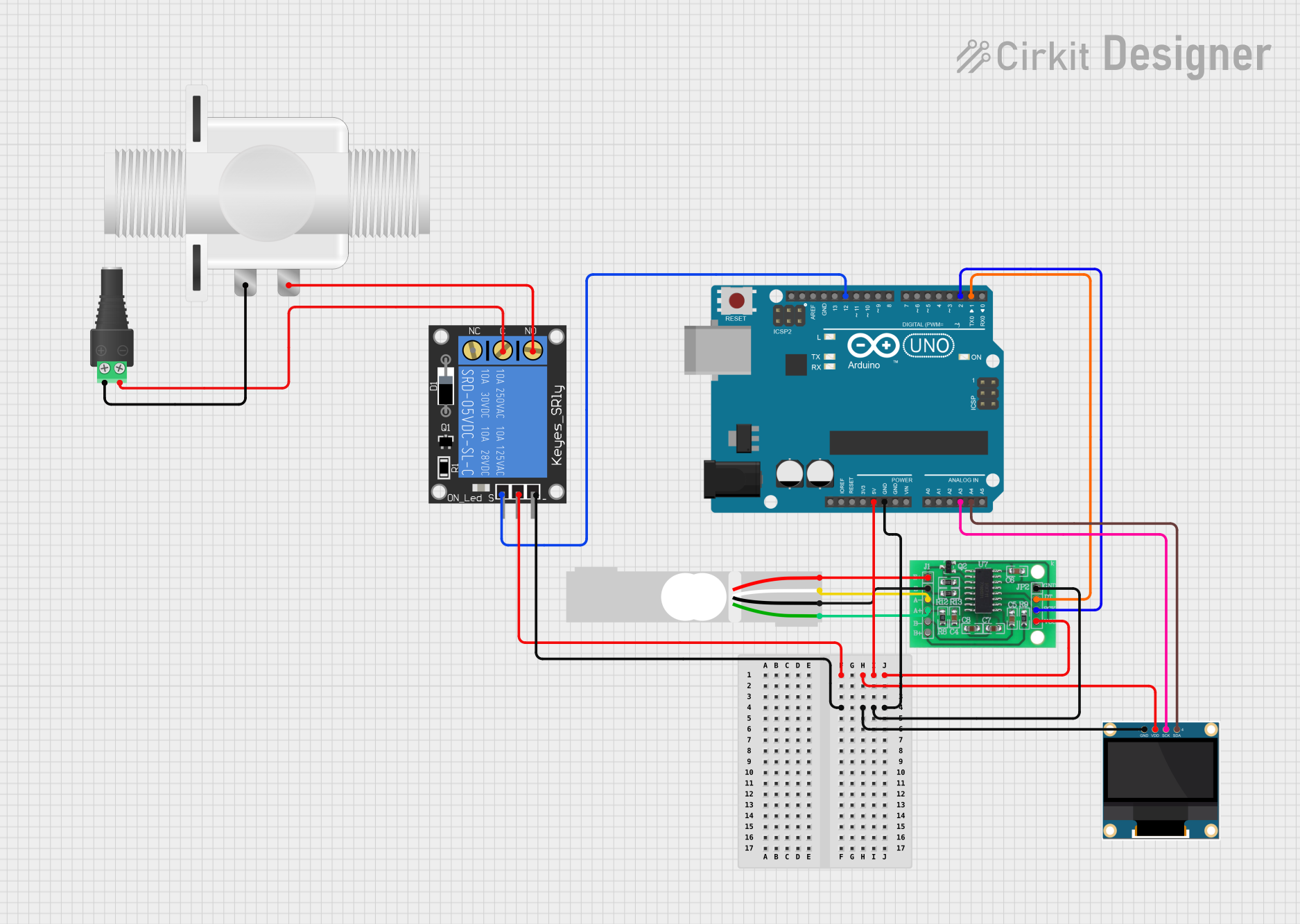
This circuit is designed to interface an Arduino UNO with a variety of components including a 0.96" OLED display, a 1-Channel Relay, a 2.1mm Barrel Jack with Terminal Block, a Plastic Solenoid Valve, a Load Cell, and an HX711 Bridge Sensor Interface. The Arduino UNO acts as the central processing unit, controlling the relay, reading data from the load cell through the HX711, and displaying information on the OLED. The relay is used to control the solenoid valve, and the barrel jack provides power to the circuit.
Component List
Arduino UNO
- Microcontroller board based on the ATmega328P
- It has 14 digital input/output pins, 6 analog inputs, a 16 MHz quartz crystal, a USB connection, a power jack, an ICSP header, and a reset button.
0.96" OLED
- A small display that uses the I2C communication protocol.
- It has four pins: GND, VDD, SCK, and SDA.
1-Channel Relay (5V 10A)
- An electromechanical switch that allows you to control high power devices with low power signals.
- It has six pins: NC, signal, C, power, NO, and ground.
2.1mm Barrel Jack with Terminal Block
- A power connector that allows you to easily attach and detach power sources.
- It has two pins: POS and NEG.
Plastic Solenoid Valve
- An electrically controlled valve used for controlling the flow of liquids or gases.
- It has two pins: pin1 and pin2.
Load Cell - Red/white/black/green
- A transducer that is used to create an electrical signal whose magnitude is directly proportional to the force being measured.
- It has four pins: E+, A-, E-, and A+.
HX711 - Bridge Sensor Interface
- A precision 24-bit analog-to-digital converter (ADC) designed for weigh scales and industrial control applications to interface directly with a bridge sensor.
- It has ten pins: E+, E-, A-, A+, B-, B+, GND - GROUND, DATA (OUT), SCK - CLOCK (IN), and 3.3/3.5V Supply.
Wiring Details
Arduino UNO
- 5V: Provides power to the OLED, Relay, and HX711.
- GND: Common ground for OLED, Relay, and HX711.
- A3: Connected to the SCK pin of the OLED for I2C communication.
- A4: Connected to the SDA pin of the OLED for I2C communication.
- D12: Connected to the signal pin of the Relay to control it.
- D2: Connected to the SCK - CLOCK (IN) pin of the HX711 for data clocking.
- D1: Connected to the DATA (OUT) pin of the HX711 to read data.
0.96" OLED
- GND: Connected to the common ground.
- VDD: Powered by the 5V from the Arduino UNO.
- SCK: Connected to A3 on the Arduino UNO for I2C communication.
- SDA: Connected to A4 on the Arduino UNO for I2C communication.
1-Channel Relay (5V 10A)
- NC: Normally closed contact, not connected in this circuit.
- Signal: Controlled by D12 on the Arduino UNO.
- C: Connected to the NEG pin of the Barrel Jack.
- Power: Powered by the 5V from the Arduino UNO.
- NO: Connected to pin2 of the Solenoid Valve.
- Ground: Connected to the common ground.
2.1mm Barrel Jack with Terminal Block
- POS: Connected to pin1 of the Solenoid Valve.
- NEG: Connected to the C pin of the Relay.
Plastic Solenoid Valve
- Pin1: Connected to the POS pin of the Barrel Jack.
- Pin2: Connected to the NO pin of the Relay.
Load Cell - Red/white/black/green
- E+: Connected to the E+ pin of the HX711.
- A-: Connected to the A- pin of the HX711.
- E-: Connected to the E- pin of the HX711.
- A+: Connected to the A+ pin of the HX711.
HX711 - Bridge Sensor Interface
- E+: Connected to the E+ pin of the Load Cell.
- E-: Connected to the E- pin of the Load Cell.
- A-: Connected to the A- pin of the Load Cell.
- A+: Connected to the A+ pin of the Load Cell.
- GND - GROUND: Connected to the common ground.
- DATA (OUT): Connected to D1 on the Arduino UNO.
- SCK - CLOCK (IN): Connected to D2 on the Arduino UNO.
- 3.3/3.5V Supply: Powered by the 5V from the Arduino UNO.
Documented Code
Arduino UNO Code (sketch.ino)
void setup() {
  // put your setup code here, to run once:

}

void loop() {
  // put your main code here, to run repeatedly:

}
Note: The provided code is a template and does not contain any functional code to operate the circuit. The user must add the necessary code to initialize the components, read sensor data, control the relay, and display information on the OLED.