
Arduino UNO Controlled DC Motor with BTS7960 Motor Driver and Voltage/Current Sensing
View and Edit Project In Cirkit Designer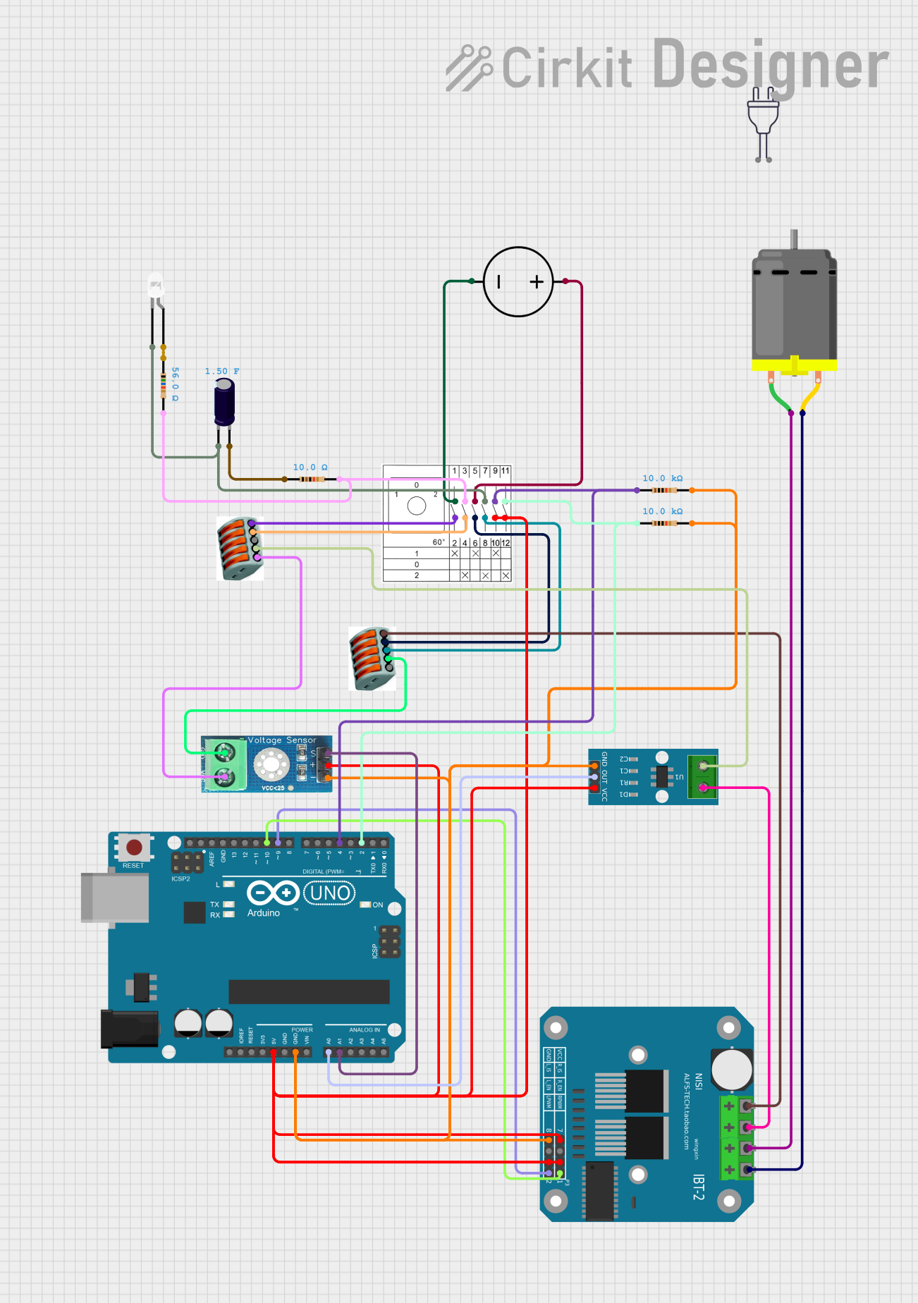
Circuit Documentation
Summary
This document provides a detailed overview of a circuit that includes a DC motor, an Arduino UNO microcontroller, a BTS7960 motor driver, various sensors, and other components. The circuit is designed to control the DC motor using the Arduino UNO, with additional functionalities provided by the sensors and other components.
Component List
DC Motor
- Description: A motor that converts electrical energy into mechanical energy.
- Pins: pin 1, pin 2
Arduino UNO
- Description: A microcontroller board based on the ATmega328P.
- Pins: UNUSED, IOREF, Reset, 3.3V, 5V, GND, Vin, A0, A1, A2, A3, A4, A5, SCL, SDA, AREF, D13, D12, D11, D10, D9, D8, D7, D6, D5, D4, D3, D2, D1, D0
BTS7960 Motor Driver
- Description: A high-current motor driver.
- Pins: Pin 1, Pin 2, Pin 3, Pin 4, Pin 5, Pin 6, Pin 7, Pin 8, Pin 9, Pin 10, Pin 11, Pin 12
DC Power Source
- Description: Provides DC power to the circuit.
- Pins: Ground, Positive
Nockenschalter
- Description: A rotary switch.
- Pins: 11, 12, 9, 10
WAGO
- Description: A terminal block for electrical connections.
- Pins: None
ACS712 Current Sensor 5A 20A 30A
- Description: Measures current in the circuit.
- Pins: 1, 2, GND, OUT, VCC
LED: Two Pin (white)
- Description: A white LED.
- Pins: cathode, anode
Electrolytic Capacitor
- Description: Stores electrical energy.
- Pins: -, +
- Properties: Capacitance: 1.5 Farads
Resistor (10k Ohms)
- Description: Limits current flow.
- Pins: pin1, pin2
- Properties: Resistance: 10,000 Ohms
Resistor (56 Ohms)
- Description: Limits current flow.
- Pins: pin1, pin2
- Properties: Resistance: 56 Ohms
Resistor (10 Ohms)
- Description: Limits current flow.
- Pins: pin1, pin2
- Properties: Resistance: 10 Ohms
Voltage Sensor DC 25V
- Description: Measures voltage in the circuit.
- Pins: +, -, output, gnd, vcc
Power 220V
- Description: Provides 220V AC power.
- Pins: hot wire, neutral wire
Wiring Details
DC Motor
- pin 1 is connected to BTS7960 Motor Driver Pin 10
- pin 2 is connected to BTS7960 Motor Driver Pin 9
Arduino UNO
- 5V is connected to:
- Nockenschalter Pin 12
- Voltage Sensor DC 25V +
- ACS712 Current Sensor 5A 20A 30A VCC
- BTS7960 Motor Driver Pin 3
- BTS7960 Motor Driver Pin 5
- BTS7960 Motor Driver Pin 7
- GND is connected to:
- Resistor pin2
- Voltage Sensor DC 25V -
- ACS712 Current Sensor 5A 20A 30A GND
- BTS7960 Motor Driver Pin 1
- A0 is connected to ACS712 Current Sensor 5A 20A 30A OUT
- A1 is connected to Voltage Sensor DC 25V output
- D10 is connected to BTS7960 Motor Driver Pin 8
- D9 is connected to BTS7960 Motor Driver Pin 4
- D4 is connected to:
- Nockenschalter Pin 9
- Resistor pin1
- D2 is connected to:
- Nockenschalter Pin 11
- Resistor pin1
BTS7960 Motor Driver
- Pin 10 is connected to DC Motor pin 1
- Pin 9 is connected to DC Motor pin 2
- Pin 3 is connected to Arduino UNO 5V
- Pin 5 is connected to Arduino UNO 5V
- Pin 7 is connected to Arduino UNO 5V
- Pin 1 is connected to:
- Arduino UNO GND
- Resistor pin2
- Voltage Sensor DC 25V -
- ACS712 Current Sensor 5A 20A 30A GND
- Pin 8 is connected to Arduino UNO D10
- Pin 4 is connected to Arduino UNO D9
- Pin 11 is connected to ACS712 Current Sensor 5A 20A 30A 1
- Pin 12 is connected to WAGO
DC Power Source
- Ground is connected to Nockenschalter
- Positive is connected to Nockenschalter
Nockenschalter
- Pin 12 is connected to Arduino UNO 5V
- Pin 10 is connected to Voltage Sensor DC 25V +
- Pin 9 is connected to:
- Arduino UNO D4
- Resistor pin1
- Pin 11 is connected to:
- Resistor pin1
- Arduino UNO D2
WAGO
- Connected to BTS7960 Motor Driver Pin 12
- Connected to Voltage Sensor DC 25V gnd
- Connected to ACS712 Current Sensor 5A 20A 30A 2
- Connected to Voltage Sensor DC 25V vcc
ACS712 Current Sensor 5A 20A 30A
- VCC is connected to Arduino UNO 5V
- GND is connected to:
- Resistor pin2
- Voltage Sensor DC 25V -
- Arduino UNO GND
- BTS7960 Motor Driver Pin 1
- OUT is connected to Arduino UNO A0
- 1 is connected to BTS7960 Motor Driver Pin 11
- 2 is connected to WAGO
LED: Two Pin (white)
- cathode is connected to:
- Electrolytic Capacitor -
- Nockenschalter
- anode is connected to Resistor pin1
Electrolytic Capacitor
- - is connected to:
- Nockenschalter
- LED: Two Pin (white) cathode
- + is connected to Resistor pin1
Resistor (10k Ohms)
- pin1 is connected to:
- Nockenschalter Pin 9
- Arduino UNO D4
- pin2 is connected to:
- Voltage Sensor DC 25V -
- ACS712 Current Sensor 5A 20A 30A GND
- Arduino UNO GND
- BTS7960 Motor Driver Pin 1
Resistor (56 Ohms)
- pin1 is connected to LED: Two Pin (white) anode
- pin2 is connected to Nockenschalter
Resistor (10 Ohms)
- pin1 is connected to Electrolytic Capacitor +
- pin2 is connected to Nockenschalter
Voltage Sensor DC 25V
- + is connected to Nockenschalter Pin 10
- - is connected to:
- Resistor pin2
- ACS712 Current Sensor 5A 20A 30A GND
- Arduino UNO GND
- BTS7960 Motor Driver Pin 1
- output is connected to Arduino UNO A1
- gnd is connected to WAGO
- vcc is connected to WAGO
Documented Code
Arduino UNO Code (sketch.ino)
void setup() {
  // put your setup code here, to run once:

}

void loop() {
  // put your main code here,