
Arduino-Controlled HVAC Automation System with Bluetooth and Real-Time Clock
View and Edit Project In Cirkit Designer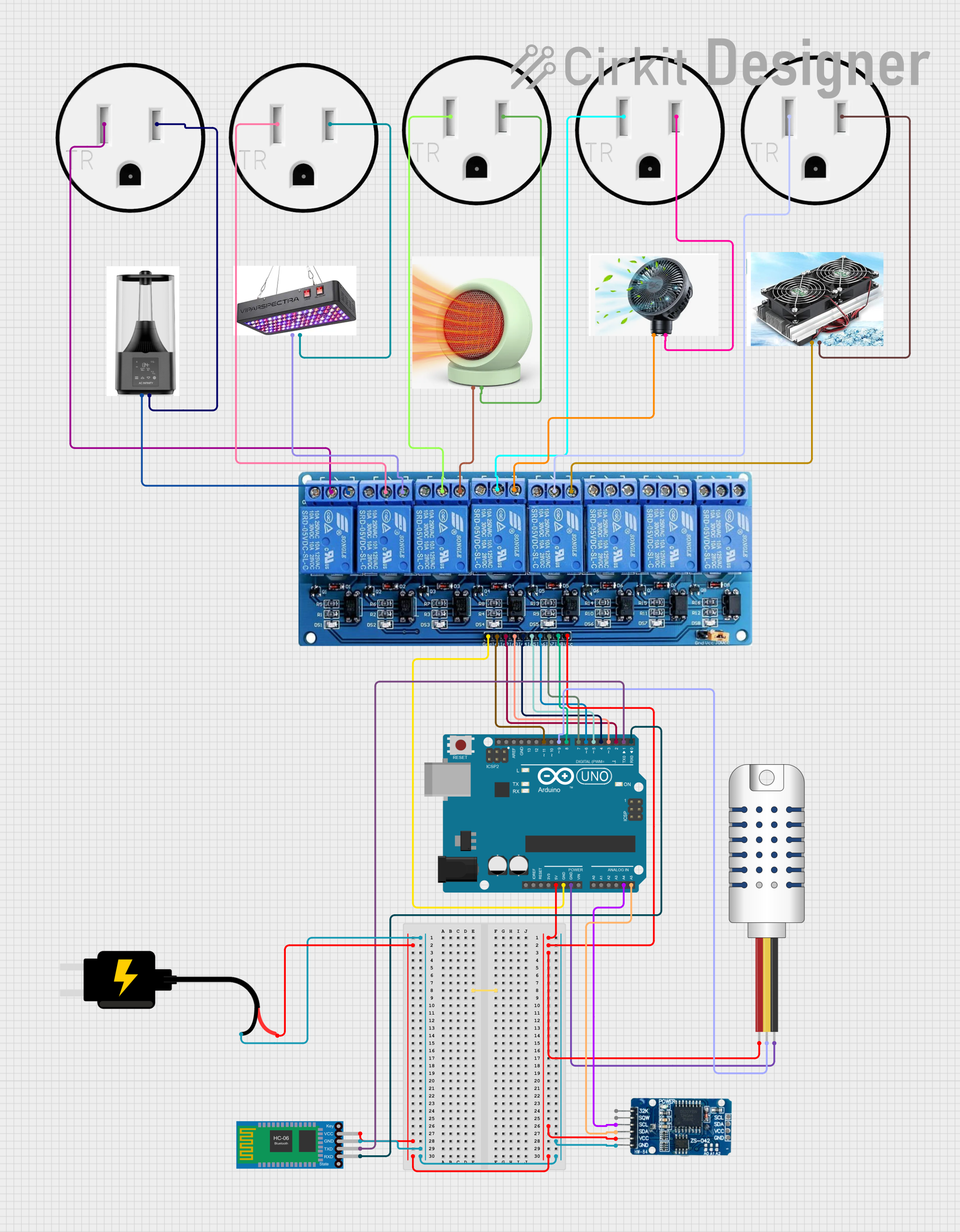
Circuit Documentation
Summary
This circuit is designed to control an HVAC system using an Arduino UNO microcontroller. The system interfaces with various components such as a 5V 8-channel relay module, an AM2302 humidity and temperature sensor, a DS3231 Real-Time Clock (RTC), and a Bluetooth HC-06 module for wireless communication. The relay module controls five AC-powered devices, including a heater, an air conditioner (AC), a fan, a light, and a humidifier. The AM2302 sensor provides environmental feedback, which is used by the Arduino to make decisions about activating or deactivating the connected devices based on temperature and humidity levels. The RTC module is used to maintain accurate time, which can be useful for time-based control scenarios. The Bluetooth module allows for remote communication with the system.
Component List
Arduino UNO
- Microcontroller board based on the ATmega328P
- Features digital I/O pins, analog input pins, and various power pins
5V 8-Channel Relay
- Relay module with 8 channels
- Allows for control of high-power devices using low-power signals from the microcontroller
AM2302 Humidity and Temperature Sensor
- Sensor for measuring humidity and temperature
- Provides digital signal output
Heater
- An AC-powered heating device
AC (Air Conditioner)
- An AC-powered air conditioning unit
Fan
- An AC-powered fan
Light
- An AC-powered light source
Humidifier
- An AC-powered device that adds moisture to the air
120V Outlet (x5)
- Standard AC power outlets for connecting AC-powered devices
Bluetooth HC-06
- Wireless Bluetooth module for serial communication
RTC DS3231
- Real-Time Clock module for timekeeping
DC Source 5V
- Power supply providing 5V DC
Wiring Details
Arduino UNO
5Vconnected to 5V power railGNDconnected to ground railA4 (SCL)connected to RTC DS3231SCLA5 (SDA)connected to RTC DS3231SDAD0 (RX)connected to Bluetooth HC-06TXDD1 (TX)connected to Bluetooth HC-06RXDD2-D8connected to 5V 8-Channel RelayIN1-IN7D9connected to AM2302DATAD11connected to 5V 8-Channel RelayIN8
5V 8-Channel Relay
VCCconnected to 5V power railGNDconnected to ground railIN1-IN8connected to Arduino UNOD2-D11C(Common) pins connected to 120V OutletAC NeutralNO(Normally Open) pins connected to respective devices (Heater, AC, Fan, Light, Humidifier)
AM2302 Humidity and Temperature Sensor
VDDconnected to 5V power railDATAconnected to Arduino UNOD9GNDconnected to ground rail
Heater, AC, Fan, Light, Humidifier
- Connected to 120V Outlets via relay module
120V Outlet
AC Neutralconnected to relay moduleCAC Hotconnected to respective devices (Heater, AC, Fan, Light, Humidifier)GNDnot connected in this context
Bluetooth HC-06
VCCconnected to 5V power railGNDconnected to ground railTXDconnected to Arduino UNOD0 (RX)RXDconnected to Arduino UNOD1 (TX)
RTC DS3231
VCCconnected to 5V power railGNDconnected to ground railSCLconnected to Arduino UNOA4 (SCL)SDAconnected to Arduino UNOA5 (SDA)
DC Source 5V
VCCconnected to 5V power railGNDconnected to ground rail
Documented Code
/*
 * This Arduino Sketch controls an HVAC system using relays and sensors.
 * The system powers on/off HVAC components based on temperature and humidity.
 * Components:
 * - 5 AC devices connected to relay channels
 * - AM2302 sensor for temperature and humidity
 * - RTC DS3231 for real-time clock
 * - Bluetooth HC-06 for communication
 */

#include <DHT.h>
#include <Wire.h>
#include <RTClib.h>

#define DHTPIN 9          // Define the pin connected to the AM2302 data pin
#define DHTTYPE DHT22     // Specify the type of DHT sensor

DHT dht(DHTPIN, DHTTYPE); // Initialize the sensor
RTC_DS3231 rtc;            // Initialize the RTC

// Array to hold the relay control pins
const int relayPins[] = {11, 2, 3, 4, 5, 6, 7, 8};

void setup() {
  Serial.begin(9600);      // Start serial communication at 9600 baud rate
  dht.begin();             // Start the DHT sensor
  if (!rtc.begin()) {
    Serial.println("Couldn't find RTC"); // Check if RTC is connected
    while (1);
  }
  if (rtc.lostPower()) {
    // Check if the RTC lost power and if so, set the time
    rtc.adjust(DateTime(F(__DATE__), F(__TIME__)));
  }
  for (int i = 0; i < 8; i++) {
    pinMode(relayPins[i], OUTPUT);       // Set relay pins as outputs
    digitalWrite(relayPins[i], HIGH);    // Initialize relays to off (active low)
  }
}

void loop() {
  float humidity = dht.readHumidity();    // Read humidity
  float temperature = dht.readTemperature(); // Read temperature
  if (isnan(humidity) || isnan(temperature)) {
    Serial.println("Failed to read from DHT sensor!"); // Check for sensor reading errors
    return;
  }
  Serial.print("Humidity: ");
  Serial.print(humidity);
  Serial.print(" %\t");
  Serial.print("Temperature: ");
  Serial.print(temperature);
  Serial.println(" *C");

  // Example control logic based on temperature and humidity
  if (temperature > 25) {
    digitalWrite(relayPins[0], LOW); // Turn on AC if temperature is above 25 degrees Celsius
  } else {
    digitalWrite(relayPins[0], HIGH); // Turn off AC otherwise
  }
  if (humidity < 40) {
    digitalWrite(relayPins[1], LOW); // Turn on Humidifier if humidity is below 40%
  } else {
    digitalWrite(relayPins[1], HIGH); // Turn off Humidifier otherwise
  }
  // Additional control logic can be added here

  delay(2000); // Wait for 2 seconds before the next loop iteration
}
This code is responsible for reading temperature and humidity data from the AM2302 sensor and controlling the AC and humidifier via the relay module based on the readings. It also initializes the RTC and sets up serial communication for debugging purposes. The relays are controlled using an array of pins, and the relays are set to an initial state of HIGH (off) since they are active low. The control logic within the loop function can be expanded to include additional functionality as needed.