
Dual Arduino UNO Controlled Relay System with I2C DAC and Stepper Motor Driver
View and Edit Project In Cirkit Designer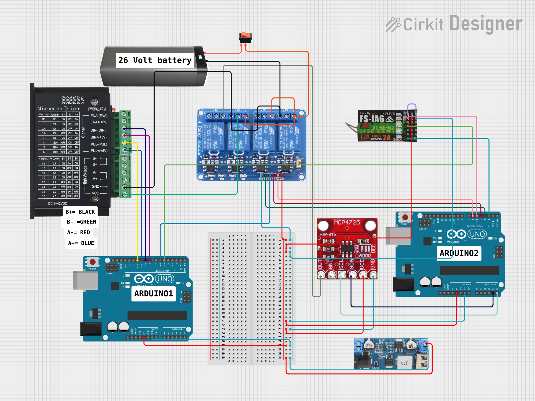
Circuit Documentation
Summary
The circuit in question is designed to interface an Arduino UNO with various peripherals including a 4-channel relay module, an I2C DAC breakout module, a micro stepping motor driver, a 6-channel receiver, and a power supply system. The circuit is powered by a 12V to 5V step-down converter and a battery pack, with a rocker switch to control power flow. The Arduino UNO microcontrollers are programmed to control the peripherals through digital and analog signals.
Component List
Arduino UNO
- Microcontroller board based on the ATmega328P.
- It has 14 digital input/output pins, 6 analog inputs, a 16 MHz quartz crystal, a USB connection, a power jack, an ICSP header, and a reset button.
Relay 4 Channel 5V
- A 4-channel relay module capable of controlling multiple devices, each channel capable of handling 5V.
xcluma MCP4725 I2C DAC Breakout Module
- A digital-to-analog converter module that interfaces with microcontrollers over the I2C bus.
tb6600 Micro Stepping Motor Driver
- A stepper motor driver that allows for precise control over stepper motors.
FLYSKY FS-IA6
- A 6-channel receiver for remote control applications.
12V to 5V Step Down Power Converter
- A power converter that steps down voltage from 9-36V to a stable 5V output.
Battery Pack
- A power source for the circuit.
Rocker Switch
- A switch to control the power supply to the circuit.
Wiring Details
Arduino UNO
- 5V: Connected to the 5V power rail which powers the relay module, I2C DAC, 6-channel receiver, and the other Arduino UNO.
- GND: Connected to the ground rail which is common for all components.
- Digital Pins (D2-D13): Various digital pins are used to interface with the relay module, stepper motor driver, and the 6-channel receiver.
- Analog Pins (A4, A5): Used for I2C communication with the DAC module.
Relay 4 Channel 5V
- VCC: Connected to the 5V power rail.
- GND: Connected to the ground rail.
- IN1-IN4: Controlled by digital pins from the Arduino UNO.
- COM1-COM4: Common pins for relay channels.
- NO1-NO4: Normally open contacts for relay channels.
- NC1-NC4: Normally closed contacts for relay channels.
xcluma MCP4725 I2C DAC Breakout Module
- VCC: Connected to the 5V power rail.
- GND: Connected to the ground rail.
- SDA, SCL: Connected to the I2C pins on the Arduino UNO.
tb6600 Micro Stepping Motor Driver
- ENA-, ENA+: Enable pins for the motor driver.
- DIR-, DIR+: Direction control pins for the motor driver.
- PUL-, PUL+: Pulse control pins for the motor driver.
- A-, A+, B-, B+: Motor connection pins.
- VCC: Connected to the relay module.
- GND: Connected to the ground rail.
FLYSKY FS-IA6
- 5V: Connected to the 5V power rail.
- GND: Connected to the ground rail.
- CH1-CH6: Channels connected to digital pins on the Arduino UNO.
12V to 5V Step Down Power Converter
- VIN 9V-36V: Input voltage from the battery pack.
- 5V OUTPUT: Connected to the 5V power rail.
- GND: Connected to the ground rail.
Battery Pack
- +: Connected to the rocker switch.
- -: Connected to the ground rail.
Rocker Switch
- Input: Connected to the positive terminal of the battery pack.
- Output: Connected to the step-down converter and the motor driver.
Documented Code
Arduino UNO (Primary Controller)
void setup() {
  // put your setup code here, to run once:

}

void loop() {
  // put your main code here, to run repeatedly:

}
Arduino UNO (Secondary Controller)
void setup() {
  // put your setup code here, to run once:

}

void loop() {
  // put your main code here, to run repeatedly:

}
Note: The actual functionality of the code is not provided in the input and would typically include initialization of I/O pins, setup of I2C communication, and the main control loop with logic to handle inputs and outputs to the various components.