
Circuit Documentation
Summary
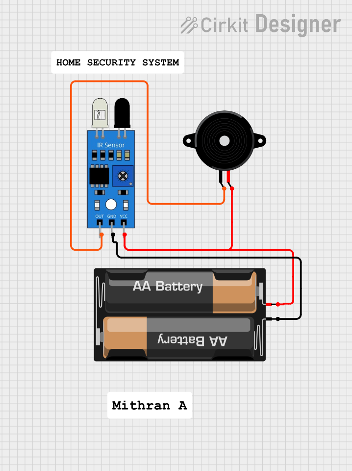
The circuit in question is a simple sensor-actuator system that consists of an infrared (IR) sensor, a piezo speaker, and a power source provided by a 2 x AA battery mount. The IR sensor detects the presence of an object or motion, and upon detection, it triggers the piezo speaker to emit a sound. The circuit does not include a microcontroller or any embedded code, indicating that the IR sensor directly drives the piezo speaker.
Component List
2 x AA Battery Mount
- Description: A battery mount for holding two AA batteries.
- Purpose: Provides the power supply for the circuit.
- Pins:
+(Positive terminal)-(Negative terminal)
IR Sensor
- Description: An infrared sensor capable of detecting objects or motion.
- Purpose: Serves as the input device that triggers the piezo speaker when an object is detected.
- Pins:
out(Output signal)gnd(Ground)vcc(Power supply input)
Piezo Speaker
- Description: An electronic component that can produce sound when an electrical signal is applied.
- Purpose: Acts as the output device that emits sound when triggered by the IR sensor.
- Pins:
pin1(Signal input)pin2(Signal ground or return path)
Wiring Details
2 x AA Battery Mount
- Positive terminal (
+) is connected to:vccpin of the IR Sensorpin2of the Piezo Speaker
- Negative terminal (
-) is connected to:gndpin of the IR Sensor
IR Sensor
outpin is connected to:pin1of the Piezo Speaker
gndpin is connected to:- Negative terminal (
-) of the 2 x AA Battery Mount
- Negative terminal (
vccpin is connected to:- Positive terminal (
+) of the 2 x AA Battery Mount
- Positive terminal (
Piezo Speaker
pin1is connected to:outpin of the IR Sensor
pin2is connected to:- Positive terminal (
+) of the 2 x AA Battery Mount
- Positive terminal (
Documented Code
There is no embedded code provided for this circuit as it does not include a microcontroller or programmable component. The functionality is purely hardware-based, with the IR sensor directly driving the piezo speaker upon detection of an object or motion.