
Arduino Mega 2560 Controlled RFID Access System with Servo Lock and Ultrasonic Sensor
View and Edit Project In Cirkit Designer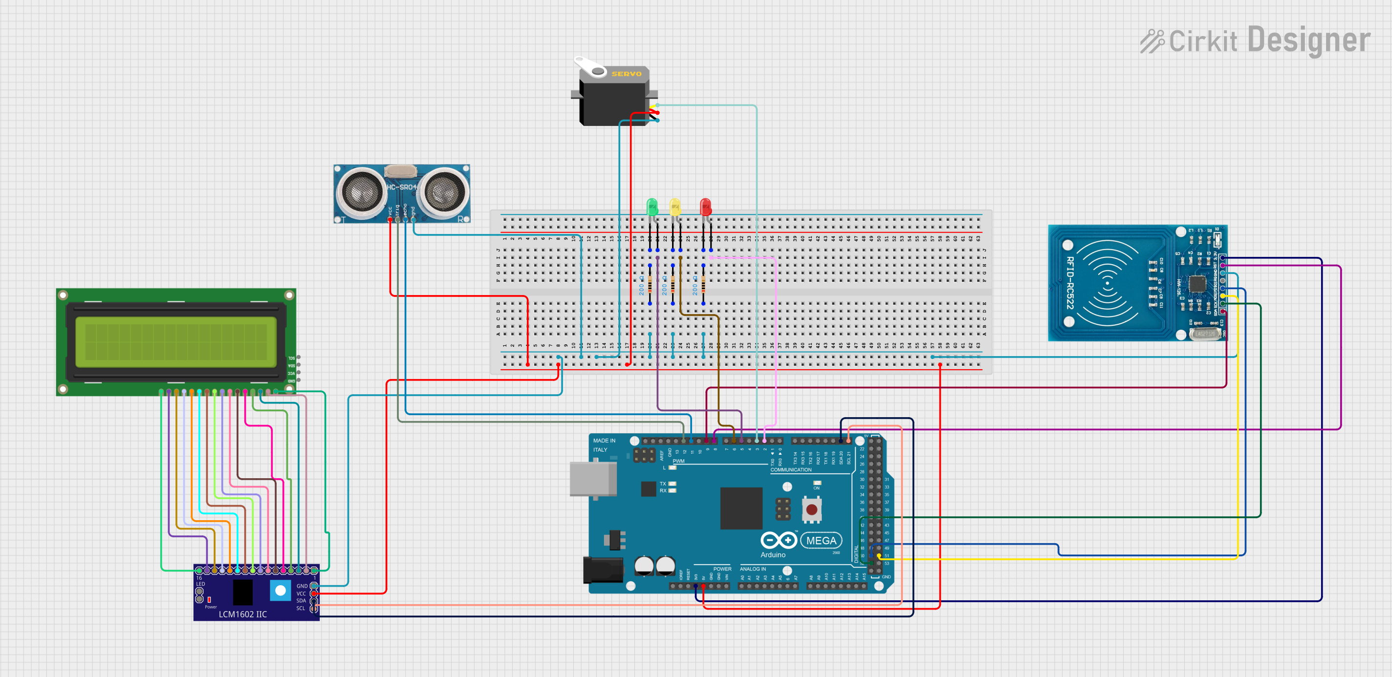
Circuit Documentation
Summary
This circuit is designed to interface various components with an Arduino Mega 2560 microcontroller. The components include a servo motor, an RFID-RC522 module, three LEDs (yellow, green, and red), an LCM1602 IIC module, resistors, an ultrasonic sensor, and an I2C LCD 16x2 screen. The circuit is powered by the Arduino Mega 2560, which also controls the components through its GPIO pins. The RFID module is used for badge detection and identification, the servo motor is likely used for some form of actuation, and the LEDs indicate status or provide user feedback. The ultrasonic sensor is used for distance measurement, and the LCD displays information or status messages.
Component List
Servo Motor
- Pins: gnd, vcc, pulse
- Description: A motor capable of precise position control.
RFID-RC522
- Pins: VCC (3.3V), RST, GND, IRQ, MISO, MOSI, SCK, SDA
- Description: An RFID reader/writer module for contactless communication.
LED: Two Pin (yellow)
- Pins: cathode, anode
- Description: A yellow light-emitting diode.
LED: Two Pin (green)
- Pins: cathode, anode
- Description: A green light-emitting diode.
LED: Two Pin (red)
- Pins: cathode, anode
- Description: A red light-emitting diode.
LCM1602 IIC
- Pins: GND, VCC, SDA, SCL, and others for interfacing with the I2C LCD 16x2 Screen
- Description: An I2C interface module for LCDs.
Arduino Mega 2560
- Pins: Multiple GPIO pins including IOREF, RESET, 3V3, 5V, GND, VIN, digital, analog, PWM, SDA, SCL, etc.
- Description: A microcontroller board based on the ATmega2560.
Resistor (200 Ohms)
- Pins: pin1, pin2
- Description: A resistor with a resistance of 200 Ohms.
Ultrasonic Sensor
- Pins: +VCC, Trigger, Echo, GND
- Description: A sensor for measuring distance via ultrasonic waves.
I2C LCD 16x2 Screen
- Pins: SCL, SDA, VCC (5V), GND, and others for interfacing with the LCM1602 IIC
- Description: A 16x2 character LCD screen with an I2C interface.
Wiring Details
Servo Motor
- GND: Connected to the ground net.
- VCC: Connected to the 5V net from the Arduino Mega 2560.
- Pulse: Connected to pin D3 PWM of the Arduino Mega 2560.
RFID-RC522
- VCC (3.3V): Connected to the 3V3 pin of the Arduino Mega 2560.
- RST: Connected to pin D8 PWM of the Arduino Mega 2560.
- GND: Connected to the ground net.
- MISO: Connected to pin D50 of the Arduino Mega 2560.
- MOSI: Connected to pin D51 of the Arduino Mega 2560.
- SCK: Connected to pin D52 of the Arduino Mega 2560.
- SDA: Connected to pin D9 PWM of the Arduino Mega 2560.
LEDs (yellow, green, red)
- Anode (yellow): Connected to pin D6 PWM of the Arduino Mega 2560.
- Anode (green): Connected to pin D5 PWM of the Arduino Mega 2560.
- Anode (red): Connected to pin D2 PWM of the Arduino Mega 2560.
- Cathode (yellow): Connected to a 200 Ohm resistor.
- Cathode (green): Connected to a 200 Ohm resistor.
- Cathode (red): Connected to a 200 Ohm resistor.
- Other end of each resistor: Connected to the ground net.
LCM1602 IIC
- GND: Connected to the ground net.
- VCC: Connected to the 5V net from the Arduino Mega 2560.
- SDA: Connected to pin D20/SDA of the Arduino Mega 2560.
- SCL: Connected to pin D21/SCL of the Arduino Mega 2560.
- Other pins: Interconnected with the I2C LCD 16x2 Screen.
Ultrasonic Sensor
- +VCC: Connected to the 5V net from the Arduino Mega 2560.
- Trigger: Connected to pin D12 PWM of the Arduino Mega 2560.
- Echo: Connected to pin D11 PWM of the Arduino Mega 2560.
- GND: Connected to the ground net.
I2C LCD 16x2 Screen
- Interconnected with the LCM1602 IIC module.
Documented Code
// Include necessary libraries
#include <Wire.h>
#include <SPI.h>
#include <LowPower.h>   // If using this library
#include <IRremote.h>
#include <Servo.h>
#include <AskSinPP/RFID.h>   // Ensure the AskSinPP library is properly installed

// Define pins for LEDs
#define LED_GREEN 3  // Pin for the green LED
#define LED_RED 4    // Pin for the red LED

// Define pins for the RFID module
#define RFID_SDA_PIN 9
#define RFID_SCL_PIN 8

// Define the RFID object type
RFID monModuleRFID(RFID_SDA_PIN, RFID_SCL_PIN);   // Define pins for the RFID module

// Define pins for the output (example relay for a door, etc.)
const int pinSortie = 5;  // Pin for the output (example)

int pin_ = 13;  // Pin for an action or a button, for example, here pin 13

// Define objects for LEDs (assuming you have a DualStatusLed class)
DualStatusLed<LED_GREEN, LED_RED> led;  // Use defined pins for LEDs

// Initialization of the RFIDDev object, if necessary
RFIDDev dev;

void setup() {
  // Initialize pins
  pinMode(pinSortie, OUTPUT);  // Make sure to set the output
  pinMode(pin_, OUTPUT);       // Make sure pin_ is well defined

  // Initialize the RFID module
  monModuleRFID.init();        // Initialize the RFID module

  // Initialize LEDs
  led.begin();

  Serial.begin(9600);  // Start serial communication for debugging
}

void loop() {
  // Check if a badge is detected
  if (monModuleRFID.isCard()) {
    Serial.println("Badge detected!");
    String badge = monModuleRFID.readCard();  // Read the badge
    Serial.print("Badge ID: ");
    Serial.println(badge);

    // Turn on the green LED if the badge is valid
    led.ledOn(500);  // Example action: turn on the green LED for 500 ms
    delay(1000);  // Wait one second before continuing
    led.ledOff();  // Turn off the LED after 1 second
  }

  // Other actions like managing the output or buttons
  test_remote_control();
  wish_output();

  // Go to sleep to save energy
  LowPower.powerDown(SLEEP_8S, ADC_OFF, BOD_OFF);
}

// Function to test the infrared remote control
void test_remote_control() {
  // Example code to test an infrared remote control
  Serial.println("Testing the infrared remote control...");
  // Logic to test the infrared remote control here
}

// Function to manage the output of a car
void wish_output() {
  // Example: check if an output is requested
  digitalWrite(pinSortie, HIGH);   // Activate the output (for example, open a door)
  delay(2000);                     // Maintain the state for 2 seconds
  digitalWrite(pinSortie, LOW);    // Deactivate the output
}

// Function to check a badge
void verification_badge() {
  if (monModuleRFID.isCard()) {  // If a badge is detected
    String badge = monModuleRFID.readCard();  // Read the badge
    Serial.print("Badge detected: ");
    Serial.println(badge);
    // Add logic here to check if the badge is valid
  }
}

// Function to learn a badge (for example, for registration)
void learn_badge() {
  if (monModuleRFID.isCard()) {  // If a badge is detected
    String badge = monModuleRFID.readCard();
    Serial.println("Registering badge...");
    // Add badge registration logic here
  }
}
This code is designed to run on the Arduino Mega 2560 and includes functionality for interfacing with an RFID module, controlling LEDs, and managing an output based on RFID badge detection. It also includes placeholder functions for testing an infrared remote control, managing an output, verifying a badge, and learning