
Arduino-Controlled Motion-Activated AC Relay for LED Rope Light
View and Edit Project In Cirkit Designer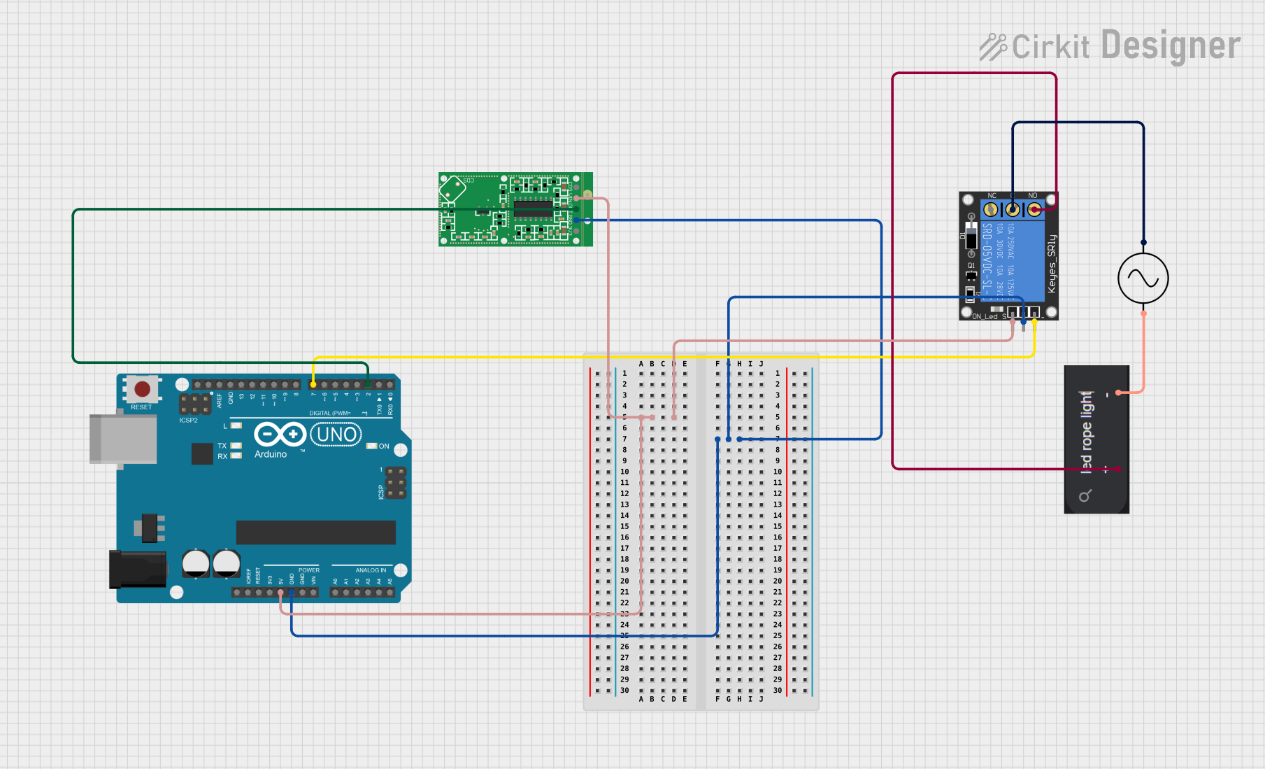
Circuit Documentation
Summary
This circuit integrates an Arduino UNO microcontroller with a 1-Channel Relay, an RCWL-0516 Microwave Radar Motion Sensor Module, an LED Rope Light, and an AC Supply. The Arduino UNO is used as the central processing unit to control the relay based on the input from the motion sensor. The relay switches an AC circuit that powers the LED Rope Light. The motion sensor detects movement and sends a signal to the Arduino, which then activates the relay to turn on the light.
Component List
Arduino UNO
- Description: A microcontroller board based on the ATmega328P.
- Pins: UNUSED, IOREF, Reset, 3.3V, 5V, GND, Vin, A0-A5, SCL, SDA, AREF, D0-D13.
1-Channel Relay (5V 10A)
- Description: A relay module capable of switching high voltage/high current loads.
- Pins: NC (Normally Closed), signal, C (Common), power, NO (Normally Open), ground.
RCWL-0516 Microwave Radar Motion Sensor Module
- Description: A motion sensor module that detects movement through microwave radar technology.
- Pins: CDS, VIN, OUT, GND, 3V3.
LED ROPE LIGHT (12V)
- Description: A flexible and waterproof LED rope light.
- Pins: positive, negative.
Ac Supply
- Description: A source of alternating current (AC) power.
- Pins: +ve (positive), -ve (negative).
Wiring Details
Arduino UNO
- 5V connected to Relay signal and Motion Sensor VIN.
- GND connected to Relay power and Motion Sensor GND.
- D7 connected to Relay ground.
- D2 connected to Motion Sensor OUT.
1-Channel Relay (5V 10A)
- Signal connected to Arduino 5V.
- Power connected to Arduino GND.
- Ground connected to Arduino D7.
- C (Common) connected to AC Supply +ve.
- NO (Normally Open) connected to LED Rope Light positive.
RCWL-0516 Microwave Radar Motion Sensor Module
- VIN connected to Arduino 5V.
- OUT connected to Arduino D2.
- GND connected to Arduino GND.
LED ROPE LIGHT (12V)
- Positive connected to Relay NO.
- Negative connected to AC Supply -ve.
Ac Supply
- +ve connected to Relay C.
- -ve connected to LED Rope Light negative.
Documented Code
Arduino UNO Code (sketch.ino)
void setup() {
  // put your setup code here, to run once:

}

void loop() {
  // put your main code here, to run repeatedly:

}
Additional Notes
- The code provided for the Arduino UNO is a template and does not contain any functional code. It needs to be populated with the logic to read the motion sensor output and control the relay accordingly.
- The documentation file for the code is empty and should be filled with relevant information as the code is developed.
This documentation provides an overview of the circuit and its components, along with the wiring details and the initial code setup for the Arduino UNO. Further development and testing are required to ensure the circuit functions as intended.