
ESP32-Controlled Robotics Platform with L298N Motor Driver and Servo Actuation
View and Edit Project In Cirkit Designer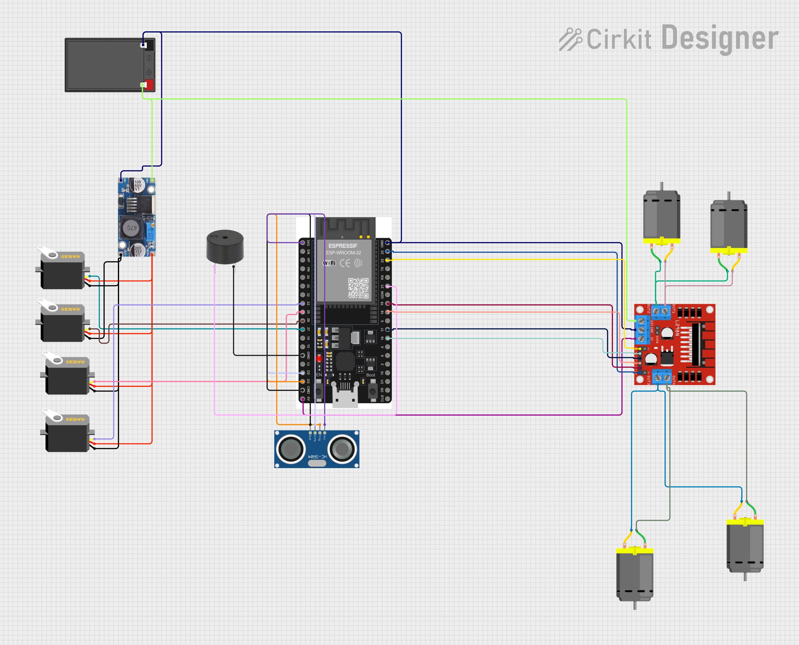
Circuit Documentation
Summary
This circuit is designed to control multiple DC motors and servos, read sensor data from an ultrasonic sensor, and provide auditory feedback through a buzzer. The main controller of the circuit is an ESP32 microcontroller, which interfaces with an L298N DC motor driver to control the motors, and directly drives the servos and buzzer. A step-down buck converter is used to regulate the voltage from a 12V 7Ah battery to a lower voltage suitable for the servos and the ESP32. The ultrasonic sensor is used for distance measurement.
Component List
Microcontroller
- ESP32 38 PINS: A microcontroller with WiFi and Bluetooth capabilities, featuring a wide range of GPIO pins for interfacing with various peripherals.
Motor Driver
- L298N DC motor driver: A module capable of driving up to two DC motors with direction and speed control.
Motors
- DC Motor: Four identical DC motors that can be controlled in terms of speed and direction.
Power Supply
- Step down Buck converter: A voltage regulator that steps down the input voltage to a lower, regulated output voltage.
- 12v 7ah Battery: A rechargeable battery providing the power source for the circuit.
Actuators
- Servo: Four servos that can be positioned at various angles using PWM signals.
Sensor
- HC-SR04 Ultrasonic Sensor: A sensor for measuring distance using ultrasonic waves.
Auditory Feedback
- Buzzer: An electronic buzzer for providing auditory signals.
Wiring Details
ESP32 38 PINS
- Ground (GND) connected to the ground of the battery, motor driver, and buck converter.
- Pin 23 (ENB) connected to the motor driver for enabling motor B.
- Pin 22/SCL (ENA) connected to the motor driver for enabling motor A.
- Pin 21/SDA connected to the buzzer.
- Pin 19 (IN4) connected to the motor driver for controlling motor input 4.
- Pin 18 (IN3) connected to the motor driver for controlling motor input 3.
- Pin 17/TX2 (IN2) connected to the motor driver for controlling motor input 2.
- Pin 16/RX2 (IN1) connected to the motor driver for controlling motor input 1.
- 3V3 pin connected to the VCC of the ultrasonic sensor.
- Pin 33 connected to the pulse pin of a servo.
- Pin 25 connected to the pulse pin of another servo.
- Pin 26 connected to the pulse pin of another servo.
- Pin 27 connected to the pulse pin of another servo.
- Pin D2 connected to the ECHO pin of the ultrasonic sensor.
- Pin D3 connected to the TRIG pin of the ultrasonic sensor.
- Pin 11 connected to the GND pin of the ultrasonic sensor.
- 5V/VIN pin connected to the 5V pin of the motor driver.
L298N DC motor driver
- OUT1 and OUT2 connected to two DC motors.
- OUT3 and OUT4 connected to two other DC motors.
- 12V pin connected to the 12V+ of the battery.
- 5V pin connected to the 5V/VIN of the ESP32.
- Ground (GND) connected to the ground of the battery and buck converter.
DC Motors
- Four DC motors connected to the OUT1, OUT2, OUT3, and OUT4 of the motor driver.
Step down Buck converter
- IN + connected to the 12V+ of the battery.
- IN - GND connected to the ground of the battery.
- OUT + connected to the VCC pins of all servos.
- OUT - GND connected to the GND pins of all servos.
12v 7ah Battery
- 12v + connected to the IN + of the buck converter and 12V pin of the motor driver.
- 12v - connected to the ground of the circuit.
Servos
- Four servos with their pulse pins connected to various GPIO pins on the ESP32 for control.
- VCC pins connected to the OUT + of the buck converter.
- GND pins connected to the OUT - GND of the buck converter.
HC-SR04 Ultrasonic Sensor
- VCC connected to the 3V3 pin of the ESP32.
- TRIG connected to the D3 pin of the ESP32.
- ECHO connected to the D2 pin of the ESP32.
- GND connected to the GND pin of the ESP32.
Buzzer
- PIN connected to the 21/SDA pin of the ESP32.
- GND connected to the ground of the ESP32.
Documented Code
No code has been provided for the microcontroller. The code would typically include initialization of the GPIO pins, setup of PWM channels for the servos, logic for motor control through the L298N driver, routines for reading the ultrasonic sensor, and control logic for the buzzer.