
ESP32-Based Smart Environmental Monitoring System with Relay Control
View and Edit Project In Cirkit Designer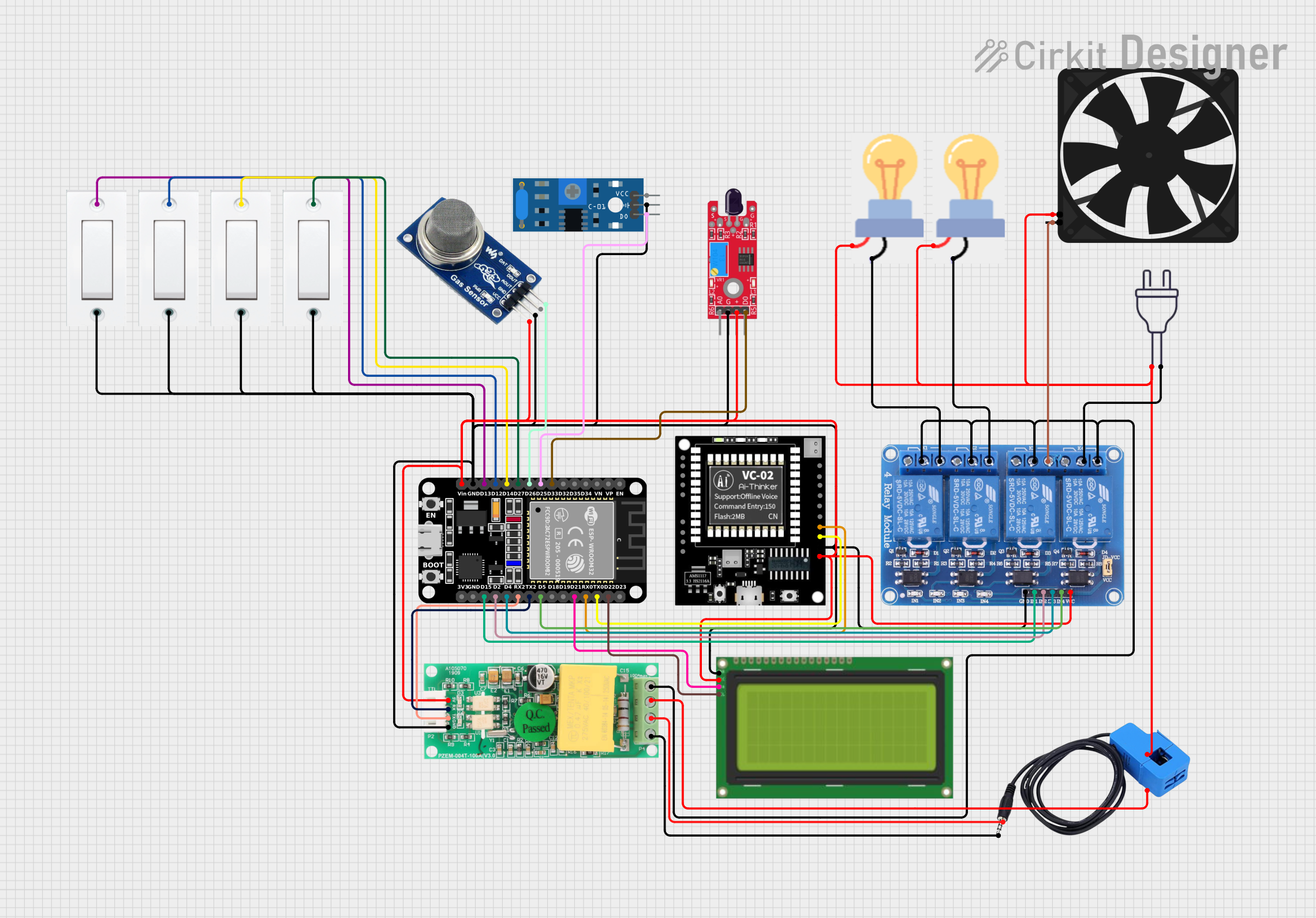
Circuit Documentation
Summary
The circuit in question appears to be a complex system involving various sensors, a microcontroller, relay modules, and other components. The primary controller is an ESP32 microcontroller, which interfaces with a PZEM004t power monitoring module, multiple flush switches, bulbs, an LCD display with I2C interface, a fan, a 4-channel relay module, a VC-02 module, a current sensor, an MQ2 gas sensor, a SW-420 vibration sensor, and a KY-026 flame sensor. The circuit is designed to monitor and control different environmental parameters and devices, likely for a smart home or industrial automation system.
Component List
PZEM004t
- Power monitoring module
- Pins: VCC, RX, TX, GND, IN, OUT
Flush Switch
- A simple on/off switch
- Pins: GND, VCC
Bulb
- An electric light bulb
- Pins: GND, power
ESP32 (30 pin)
- A microcontroller with WiFi and Bluetooth capabilities
- Pins: EN, VP, VN, D34, D35, D32, D33, D25, D26, D27, D14, D12, D13, GND, Vin, D23, D22, TX0, RX0, D21, D19, D18, D5, TX2, RX2, D4, D2, D15, 3V3
Power 220v
- Mains power supply
- Pins: hot wire, neutral wire
Lcd 20x4 i2c
- An LCD display with an I2C interface
- Pins: GND, 5v, SCA, SCL
Fan
- An electric fan
- Pins: GND, 5V
Relay 4 Channel 5v
- A 4-channel relay module for controlling high power devices
- Pins: GND, IN1, IN2, IN3, IN4, VCC, COM1, COM2, COM3, COM4, NO1, NO2, NO3, NO4, NC1, NC2, NC3, NC4
VC-02 Module
- A communication module
- Pins: NC, TCK OR IOB0, TMS OR IOB1, GND, Vcc, DAC_L, DAS_R, 3.3V O, SDA_5V, SCL_5V, SDA OR IOB3, SCL OR IOB2, IOA27, IOB8, RX(IOB6), TX(IOB7)
Current Sensor
- A sensor for measuring electric current
- Pins: Out, Burden, In_current, Out_current
MQ2
- A gas sensor for detecting LPG, propane, hydrogen, and more
- Pins: VCC, GND, AOUT, DOUT
SW-420 Vibration Sensor
- A sensor for detecting vibrations
- Pins: vcc, Ground, Digital output
KY-026 Flame Sensor
- A sensor for detecting flames
- Pins: AO, GND, VCC, DO
Wiring Details
PZEM004t
- VCC: Connected to the 5V power rail
- RX: Connected to TX2 of ESP32
- TX: Connected to RX2 of ESP32
- GND: Connected to the ground rail
- IN: Connected to the Out_current of the current sensor
- OUT: Connected to the NO4, COM1, COM2, COM3 of the Relay 4 Channel 5v
Flush Switch
- GND: Connected to the ground rail
- VCC: Connected to the 5V power rail and various pins on the ESP32 (D27, D14, D12, D13)
Bulb
- GND: Connected to NO1 and NO2 of the Relay 4 Channel 5v
- Power: Connected to the hot wire of the power 220v and In_current of the current sensor
ESP32 (30 pin)
- Vin: Connected to the 5V power rail
- GND: Connected to the ground rail
- TX2: Connected to RX of PZEM004t
- RX2: Connected to TX of PZEM004t
- D33: Connected to DO of KY-026 Flame Sensor
- D25: Connected to Digital output of SW-420 Vibration Sensor
- D26: Connected to DOUT of MQ2
- D27: Connected to VCC of a Flush Switch
- D14: Connected to VCC of a Flush Switch
- D12: Connected to VCC of a Flush Switch
- D13: Connected to VCC of a Flush Switch
- D22: Connected to SCL of Lcd 20x4 i2c
- TX0: Connected to TX(IOB7) of VC-02 Module
- RX0: Connected to RX(IOB6) of VC-02 Module
- D21: Connected to SCA of Lcd 20x4 i2c
- D5: Connected to IN4 of Relay 4 Channel 5v
- D4: Connected to IN3 of Relay 4 Channel 5v
- D2: Connected to IN2 of Relay 4 Channel 5v
- D15: Connected to IN1 of Relay 4 Channel 5v
Power 220v
- Neutral wire: Connected to COM4 of Relay 4 Channel 5v
- Hot wire: Connected to power of bulbs, In_current of the current sensor, and 5V of the fan
Lcd 20x4 i2c
- GND: Connected to the ground rail
- 5v: Connected to the 5V power rail
- SCA: Connected to D21 of ESP32
- SCL: Connected to D22 of ESP32
Fan
- GND: Connected to NO3 of Relay 4 Channel 5v
- 5V: Connected to the hot wire of the power 220v
Relay 4 Channel 5v
- GND: Connected to the ground rail
- VCC: Connected to the 5V power rail
- IN1: Connected to D15 of ESP32
- IN2: Connected to D2 of ESP32
- IN3: Connected to D4 of ESP32
- IN4: Connected to D5 of ESP32
- COM1, COM2, COM3: Connected to OUT of PZEM004t
- COM4: Connected to neutral wire of power 220v
- NO1: Connected to GND of bulb
- NO2: Connected to GND of another bulb
- NO3: Connected to GND of the fan
- NO4: Connected to OUT of PZEM004t
VC-02 Module
- GND: Connected to the ground rail
- Vcc: Connected to the 5V power rail
- TX(IOB7): Connected to TX0 of ESP32
- RX(IOB6): Connected to RX0 of ESP32
Current Sensor
- Out: Connected to OUT of PZEM004t
- Burden: Connected to IN of PZEM004t
- In_current: Connected to power of the bulbs
- Out_current: Connected to IN of PZEM004t
MQ2
- VCC: Connected to the 5V power rail
- GND: Connected to the ground rail
- AOUT: Not connected
- DOUT: Connected to D26 of ESP32
SW-420 Vibration Sensor
- vcc: Connected to the 5V power rail
- Ground: Connected to the ground rail
- Digital output: Connected to D25 of ESP32
KY-026 Flame Sensor
- AO: Not connected
- GND: Connected to the ground rail
- VCC: Connected to the 5V power rail
- DO: Connected to D33 of ESP32
Documented Code
No code was provided for the microcontrollers in the circuit. Therefore, this section is left blank until the relevant code is supplied.