Cirkit Designer
Your all-in-one circuit design IDE
Home /
Project Documentation
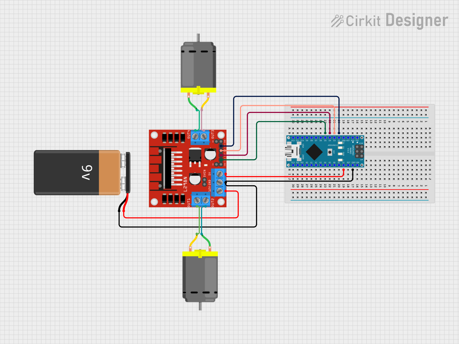
Arduino Nano Controlled Dual DC Motor Driver Circuit
Circuit Documentation
Summary of the Circuit
This circuit is designed to control two DC motors using an Arduino Nano microcontroller and an L298N DC motor driver. The Arduino Nano is responsible for sending control signals to the L298N driver, which in turn drives the motors. A 9V battery provides the power source for the motors and the motor driver, while the Arduino Nano is powered by the regulated 5V output from the L298N.
Component List
Arduino Nano
- Microcontroller board based on the ATmega328P
- It has a variety of digital and analog I/O pins for interfacing with various components and sensors.
- The board can be powered via USB or an external power source.
L298N DC Motor Driver
- A dual H-bridge motor driver capable of driving two DC motors or one stepper motor.
- It has inputs for motor control signals and can provide a regulated 5V output.
9V Battery
- Provides the power supply for the motor driver and, indirectly, the motors.
- It is connected to the motor driver's power input.
DC Motor (2x)
- Standard DC motors that are driven by the L298N motor driver.
- Each motor has two connections, one for each terminal.
Wiring Details
Arduino Nano
- GND: Connected to the ground of the 9V battery and the GND of the L298N motor driver.
- 5V: Provides power to the L298N motor driver's 5V input.
- D2 - D5: Digital pins used to send control signals to the L298N motor driver's IN1 - IN4 inputs.
L298N DC Motor Driver
- GND: Connected to the ground of the 9V battery and the GND of the Arduino Nano.
- 5V: Powered by the 5V output from the Arduino Nano.
- IN1 - IN4: Control inputs connected to the D2 - D5 outputs of the Arduino Nano.
- OUT1 - OUT4: Motor outputs connected to the two DC motors.
- 12V: Connected to the positive terminal of the 9V battery to power the motors.
9V Battery
- +: Connected to the 12V input of the L298N motor driver.
- -: Connected to the GND of the Arduino Nano and the L298N motor driver.
DC Motor 1
- pin 1: Connected to OUT3 of the L298N motor driver.
- pin 2: Connected to OUT4 of the L298N motor driver.
DC Motor 2
- pin 1: Connected to OUT1 of the L298N motor driver.
- pin 2: Connected to OUT2 of the L298N motor driver.
Documented Code
Arduino Nano Code (sketch.ino)
void setup() {
  // put your setup code here, to run once:

}

void loop() {
  // put your main code here, to run repeatedly:

}
This code is a template for the Arduino Nano. The setup() function is called once when the microcontroller starts, and the loop() function is called repeatedly, allowing the microcontroller to perform operations continuously. The user should add the specific control code for the motors within these functions.