Arduino UNO Controlled Traffic Light System
Traffic Light Control Circuit Documentation
Summary
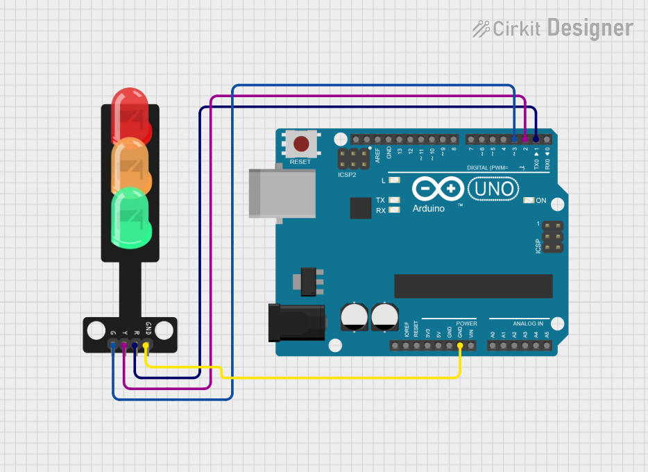
This document describes a simple traffic light control circuit that is designed to operate a three-color traffic light system using an Arduino UNO microcontroller. The circuit controls the green, yellow, and red LEDs of a traffic light to illuminate in a specific sequence, simulating a standard traffic light operation. The green LED is on for 5 seconds, followed by the yellow LED for 2 seconds, and then the red LED for 5 seconds. This cycle repeats indefinitely.
Component List
Arduino UNO
- Description: A microcontroller board based on the ATmega328P.
- Pins Used: GND, D3, D2, D1.
- Purpose: Acts as the central controller for the traffic light system, driving the LEDs and managing the timing sequence.
Traffic Light
- Description: A simple traffic light module with three LEDs (Green, Yellow, Red).
- Pins Used: Green, Yellow, Red, GND.
- Purpose: Represents the traffic light, with each LED corresponding to a light on a standard traffic signal.
Wiring Details
Arduino UNO
- GND: Connected to the GND pin of the Traffic Light.
- D3: Connected to the Green pin of the Traffic Light.
- D2: Connected to the Yellow pin of the Traffic Light.
- D1: Connected to the Red pin of the Traffic Light.
Traffic Light
- Green: Connected to pin D3 on the Arduino UNO.
- Yellow: Connected to pin D2 on the Arduino UNO.
- Red: Connected to pin D1 on the Arduino UNO.
- GND: Connected to the GND pin on the Arduino UNO.
Documented Code
/*
 * This Arduino sketch controls a traffic light system.
 * The green LED is on for 5 seconds, followed by the yellow LED for 2 seconds,
 * and then the red LED for 5 seconds. This cycle repeats indefinitely.
 */

// Pin definitions
const int greenPin = 3;
const int yellowPin = 2;
const int redPin = 1;

void setup() {
  // Initialize the digital pins as outputs
  pinMode(greenPin, OUTPUT);
  pinMode(yellowPin, OUTPUT);
  pinMode(redPin, OUTPUT);
}

void loop() {
  // Turn on the green LED
  digitalWrite(greenPin, HIGH);
  delay(5000); // Wait for 5 seconds
  digitalWrite(greenPin, LOW);

  // Turn on the yellow LED
  digitalWrite(yellowPin, HIGH);
  delay(2000); // Wait for 2 seconds
  digitalWrite(yellowPin, LOW);

  // Turn on the red LED
  digitalWrite(redPin, HIGH);
  delay(5000); // Wait for 5 seconds
  digitalWrite(redPin, LOW);
}
File Name: sketch.ino
Description: The code provided is an Arduino sketch that defines three output pins corresponding to the green, yellow, and red LEDs of the traffic light. The setup() function initializes these pins as outputs. The loop() function then controls the state of each LED, turning them on and off in sequence with specified delays to create the traffic light timing pattern.