Arduino Ultrasonic Sensor-Based Battery Level Indicator with Buzzer
Circuit Documentation
Summary
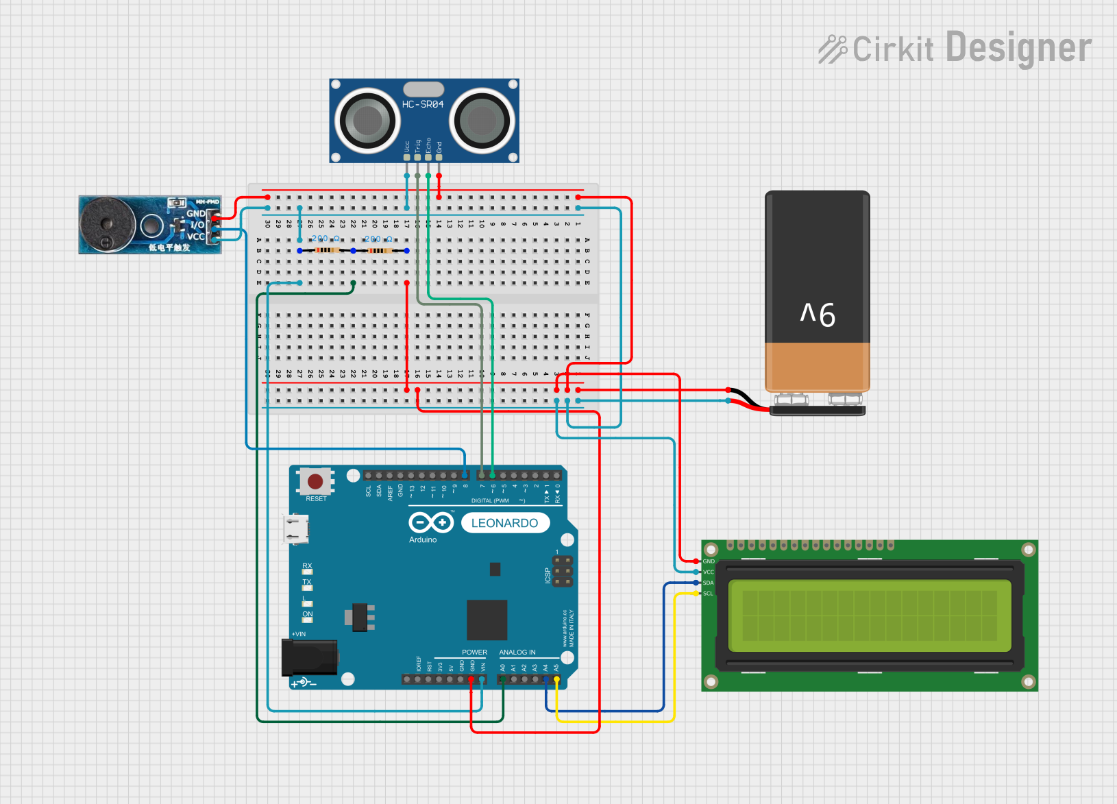
This circuit is designed to utilize an Arduino Leonardo microcontroller to interface with a 16x2 I2C LCD, an HC-SR04 Ultrasonic Sensor, a Buzzer Module, and a 9V Battery. The system displays the remaining battery percentage on the LCD and emits a sound through the buzzer when an object is detected within 100 cm of the sensor. The buzzer frequency increases as the object gets closer, providing an auditory indication of proximity.
Component List
Arduino Leonardo (Rev3b)
- Description: A microcontroller board based on the ATmega32u4.
- Purpose: Acts as the main controller for the circuit, processing inputs from the ultrasonic sensor and controlling the LCD and buzzer.
16x2 I2C LCD
- Description: A liquid crystal display that can show 16 characters per line and has 2 lines.
- Purpose: Displays the remaining battery percentage.
9V Battery
- Description: A standard 9V battery used to power the circuit.
- Purpose: Provides the necessary voltage for the components.
HC-SR04 Ultrasonic Sensor
- Description: An ultrasonic distance sensor that measures distance by emitting sound waves.
- Purpose: Detects the distance to nearby objects and provides input to the microcontroller.
Buzzer Module
- Description: A simple sound-emitting device.
- Purpose: Emits sound based on the distance detected by the ultrasonic sensor.
Resistor (200 Ohm)
- Description: A passive electrical component that resists the flow of current.
- Purpose: Used in the circuit to limit current and protect components.
Wiring Details
Arduino Leonardo (Rev3b)
GND: Connected to GND of the 9V Battery, 16x2 I2C LCD, HC-SR04 Ultrasonic Sensor, and Buzzer Module.
A0: Connected to pin2 of the first Resistor for battery voltage reading.
VIN: Connected to pin1 of the first Resistor, which is connected to VCC of the HC-SR04 Ultrasonic Sensor, Vcc of the Buzzer Module, and VCC of the 16x2 I2C LCD.
D6 PWM/A7: Connected to ECHO pin of the HC-SR04 Ultrasonic Sensor.
D7: Connected to TRIG pin of the HC-SR04 Ultrasonic Sensor.
A4: Connected to SDA pin of the 16x2 I2C LCD.
A5: Connected to SCL pin of the 16x2 I2C LCD.
D8/A8: Connected to I/O pin of the Buzzer Module.
16x2 I2C LCD
GND: Connected to GND of the Arduino Leonardo and 9V Battery.
VCC: Connected to VIN of the Arduino Leonardo.
SDA: Connected to A4 of the Arduino Leonardo.
SCL: Connected to A5 of the Arduino Leonardo.
9V Battery
-: Connected to GND of the Arduino Leonardo, 16x2 I2C LCD, HC-SR04 Ultrasonic Sensor, and Buzzer Module.
+: Connected to VIN of the Arduino Leonardo, pin1 of the first Resistor, which is also connected to VCC of the HC-SR04 Ultrasonic Sensor, Vcc of the Buzzer Module, and VCC of the 16x2 I2C LCD.
HC-SR04 Ultrasonic Sensor
GND: Connected to GND of the Arduino Leonardo and 9V Battery.
VCC: Connected to VIN of the Arduino Leonardo.
TRIG: Connected to D7 of the Arduino Leonardo.
ECHO: Connected to D6 PWM/A7 of the Arduino Leonardo.
Buzzer Module
GND: Connected to GND of the Arduino Leonardo and 9V Battery.
Vcc: Connected to VIN of the Arduino Leonardo.
I/O: Connected to D8/A8 of the Arduino Leonardo.
Resistor (200 Ohm)
pin1: Connected to VIN of the Arduino Leonardo.
pin2: Connected to pin2 of the second Resistor and A0 of the Arduino Leonardo.
Documented Code
Arduino Leonardo Code
/*
 * This Arduino Sketch is designed to work with an Arduino Leonardo, a 16x2 I2C LCD,
 * an HC-SR04 Ultrasonic Sensor, and a Buzzer Module. The LCD displays the remaining
 * battery percentage, and the buzzer emits a sound if an object is detected within
 * 100 cm of the sensor. The buzzer frequency increases as the object gets closer.
 */

#include <Wire.h>
#include <LiquidCrystal_I2C.h>

// Initialize the LCD with I2C address 0x20, 16 columns, and 2 rows
LiquidCrystal_I2C lcd(0x20, 16, 2);

// Analog pin for reading battery voltage
const int analogPin = A0;
float voltage = 0.0;
int percentage = 0;

// Pins for Ultrasonic Sensor and Buzzer
const int trigPin = 7;
const int echoPin = 6;
const int buzzerPin = 8;

void setup() {
  // Initialize the LCD
  lcd.init();
  lcd.backlight();
  lcd.setCursor(0, 0);
  lcd.print("Battery Level:");

  // Set pin modes for Ultrasonic Sensor and Buzzer
  pinMode(trigPin, OUTPUT);
  pinMode(echoPin, INPUT);
  pinMode(buzzerPin, OUTPUT);

  Serial.begin(9600); // For debugging
}

void loop() {
  // Read battery voltage
  int sensorValue = analogRead(analogPin);
  voltage = sensorValue * (4.0 / 1023.0) * (9.0 / 4.0); // Voltage divider
  percentage = (int)(((voltage - 6.0) / (9.0 - 6.0)) * 100.0);
  if (percentage > 100) percentage = 100;
  if (percentage < 0) percentage = 0;

  // Display battery percentage on LCD
  lcd.setCursor(0, 1);
  lcd.print(percentage);
  lcd.print("%    "); // Clear remaining characters

  // Read distance from Ultrasonic Sensor
  float distance = readDistance();
  Serial.print("Distance: ");
  Serial.print(distance);
  Serial.println(" cm");

  // Control buzzer based on distance
  manageBuzzer(distance);

  delay(500); // Delay for 0.5 seconds
}

float readDistance() {
  digitalWrite(trigPin, LOW);
  delayMicroseconds(2); // Stabilize line
  digitalWrite(trigPin, HIGH);
  delayMicroseconds(10); // Trigger pulse
  digitalWrite(trigPin, LOW);

  long duration = pulseIn(echoPin, HIGH); // Read echo pulse
  return duration / 58.0; // Convert to cm
}

void manageBuzzer(float distance) {
  if (distance <= 100) {
    int frequency = map(distance, 0, 100, 2000, 200); // Map distance to frequency
    tone(buzzerPin, frequency, 100); // Emit tone
  } else {
    noTone(buzzerPin); // Stop tone
  }
}
9V Battery Code
void setup() {
  // put your setup code here, to run once:

}

void loop() {
  // put your main code here, to run repeatedly:

}
16x2 I2C LCD Code
// No specific code for the LCD as it is controlled by the Arduino Leonardo.
This documentation provides a comprehensive overview of the circuit, detailing the components, their connections, and the code that drives the functionality of the system.