
Wi-Fi Enabled Soil Moisture Monitoring System with NodeMCU and Soil Moisture Sensor
View and Edit Project In Cirkit Designer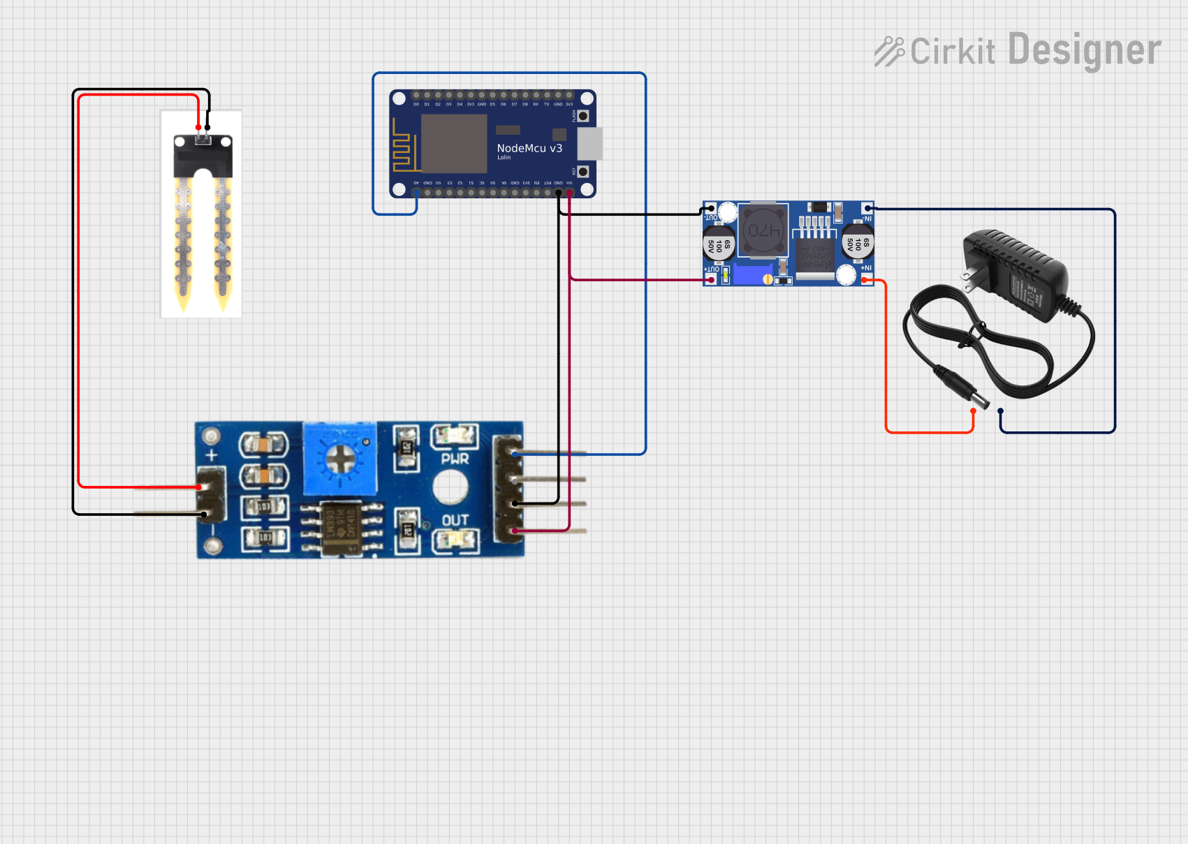
Circuit Documentation
Summary
This circuit is designed to measure soil moisture levels using a soil moisture sensor and a Soil Moisture Module. The data is processed by a NodeMCU V3 ESP8266 microcontroller, which reads the analog values from the sensor and outputs the soil moisture percentage to the serial monitor. The circuit is powered by a 12V power supply, which is regulated to the required voltage levels using a buck converter.
Component List
Soil Moisture Sensor
- Description: Measures the moisture level in the soil.
- Pins: Positive, Negative
Soil Moisture Module
- Description: Interfaces with the soil moisture sensor and provides analog and digital outputs.
- Pins: Positive, Negative, Analog, Digital, Ground, VCC
NodeMCU V3 ESP8266
- Description: A microcontroller with built-in Wi-Fi capabilities, used to read sensor data and process it.
- Pins: A0, GND, VU, S3, S2, S1, SC, S0, SK, 3V3, EN, RST, Vin, D0, D1, D2, D3, D4, D5, D6, D7, D8, RX, TX
Buck Converter
- Description: Steps down the voltage from the 12V power supply to the required levels for the other components.
- Pins: IN+, IN-, OUT+, OUT-
12V Power Supply
- Description: Provides the primary power source for the circuit.
- Pins: +, -
Wiring Details
Soil Moisture Sensor
- Positive: Connected to the Positive pin of the Soil Moisture Module.
- Negative: Connected to the Negative pin of the Soil Moisture Module.
Soil Moisture Module
- Positive: Connected to the Positive pin of the Soil Moisture Sensor.
- Negative: Connected to the Negative pin of the Soil Moisture Sensor.
- Analog: Connected to the A0 pin of the NodeMCU V3 ESP8266.
- Ground: Connected to the OUT- pin of the Buck Converter and the GND pin of the NodeMCU V3 ESP8266.
- VCC: Connected to the OUT+ pin of the Buck Converter and the Vin pin of the NodeMCU V3 ESP8266.
NodeMCU V3 ESP8266
- A0: Connected to the Analog pin of the Soil Moisture Module.
- GND: Connected to the Ground pin of the Soil Moisture Module and the OUT- pin of the Buck Converter.
- Vin: Connected to the VCC pin of the Soil Moisture Module and the OUT+ pin of the Buck Converter.
Buck Converter
- IN+: Connected to the + pin of the 12V Power Supply.
- IN-: Connected to the - pin of the 12V Power Supply.
- OUT+: Connected to the VCC pin of the Soil Moisture Module and the Vin pin of the NodeMCU V3 ESP8266.
- OUT-: Connected to the Ground pin of the Soil Moisture Module and the GND pin of the NodeMCU V3 ESP8266.
12V Power Supply
- +: Connected to the IN+ pin of the Buck Converter.
- -: Connected to the IN- pin of the Buck Converter.
Code Documentation
NodeMCU V3 ESP8266 Code
#define SOIL_PIN A0 // Analog pin connected to soil sensor

void setup() {
  Serial.begin(115200);
}

void loop() {
  int sensorValue = analogRead(SOIL_PIN); // Read analog value (0-1023)

  // Map the value to percentage (adjust range based on your sensor calibration)
  int moisturePercent = map(sensorValue, 1023, 0, 0, 100);

  Serial.print("Soil Moisture: ");
  Serial.print(moisturePercent);
  Serial.println(" %");

  delay(1000); // Wait 1 second before the next reading
}
This code initializes the serial communication at a baud rate of 115200. In the loop function, it reads the analog value from the soil moisture sensor, maps it to a percentage, and prints the soil moisture percentage to the serial monitor every second.