
Arduino UNO Controlled Robot with Bluetooth and Ultrasonic Sensor
View and Edit Project In Cirkit Designer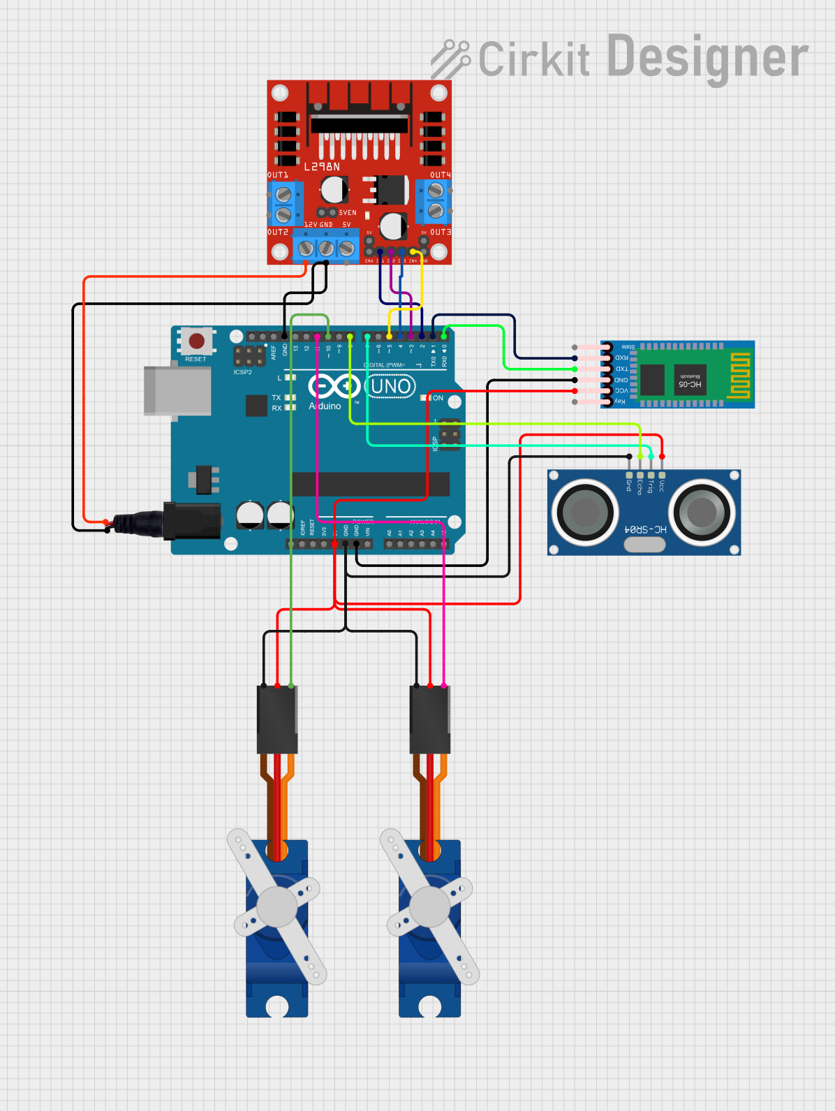
Circuit Documentation
Summary
This document provides a detailed overview of a circuit designed to control DC motors, interface with an ultrasonic sensor, and communicate via Bluetooth. The circuit utilizes an Arduino UNO as the central microcontroller to manage inputs and outputs, including driving motors through an L298N DC motor driver, reading distance measurements from an HC-SR04 Ultrasonic Sensor, and interfacing with an HC-05 Bluetooth Module for wireless communication. Additionally, the circuit includes two Tower Pro SG90 servos for precise angular movement.
Component List
L298N DC Motor Driver
- Description: A motor driver module capable of driving two DC motors or one stepper motor.
- Pins: OUT1, OUT2, 12V, GND, 5V, OUT3, OUT4, 5V-ENA-JMP-I, 5V-ENA-JMP-O, +5V-J1, +5V-J2, ENA, IN1, IN2, IN3, IN4, ENB
Power Jack
- Description: A connector for supplying power to the circuit.
- Pins: POSITIF, NEGATIF
HC-05 Bluetooth Module
- Description: A wireless communication module for Bluetooth connectivity.
- Pins: Key, VCC, GND, TXD, RXD, State
Arduino UNO
- Description: A microcontroller board based on the ATmega328P.
- Pins: UNUSED, IOREF, Reset, 3.3V, 5V, GND, Vin, A0, A1, A2, A3, A4, A5, SCL, SDA, AREF, D13, D12, D11, D10, D9, D8, D7, D6, D5, D4, D3, D2, D1, D0
HC-SR04 Ultrasonic Sensor
- Description: An ultrasonic distance sensor capable of measuring distances by emitting ultrasonic waves.
- Pins: VCC, TRIG, ECHO, GND
Tower Pro SG90 Servo (x2)
- Description: A small and lightweight servo motor for precise control.
- Pins: Signal, +5V, GND
Wiring Details
L298N DC Motor Driver
- 12V connected to Power Jack POSITIF
- GND connected to Power Jack NEGATIF
- IN1 connected to Arduino UNO D2
- IN2 connected to Arduino UNO D3
- IN3 connected to Arduino UNO D4
- IN4 connected to Arduino UNO D5
Power Jack
- POSITIF connected to L298N DC Motor Driver 12V
- NEGATIF connected to Arduino UNO GND and L298N DC Motor Driver GND
HC-05 Bluetooth Module
- VCC connected to Arduino UNO 5V
- GND connected to Arduino UNO GND
- TXD connected to Arduino UNO D0
- RXD connected to Arduino UNO D1
Arduino UNO
- 5V connected to HC-05 Bluetooth Module VCC, HC-SR04 Ultrasonic Sensor VCC, and both Tower Pro SG90 Servos +5V
- GND connected to HC-05 Bluetooth Module GND, HC-SR04 Ultrasonic Sensor GND, and both Tower Pro SG90 Servos GND
- D0 connected to HC-05 Bluetooth Module TXD
- D1 connected to HC-05 Bluetooth Module RXD
- D2 connected to L298N DC Motor Driver IN1
- D3 connected to L298N DC Motor Driver IN2
- D4 connected to L298N DC Motor Driver IN3
- D5 connected to L298N DC Motor Driver IN4
- D7 connected to HC-SR04 Ultrasonic Sensor TRIG
- D8 connected to HC-SR04 Ultrasonic Sensor ECHO
- D10 connected to Tower Pro SG90 Servo (Instance 1) Signal
- D11 connected to Tower Pro SG90 Servo (Instance 2) Signal
HC-SR04 Ultrasonic Sensor
- VCC connected to Arduino UNO 5V
- TRIG connected to Arduino UNO D7
- ECHO connected to Arduino UNO D8
- GND connected to Arduino UNO GND
Tower Pro SG90 Servo (Instance 1)
- Signal connected to Arduino UNO D10
- +5V connected to Arduino UNO 5V
- GND connected to Arduino UNO GND
Tower Pro SG90 Servo (Instance 2)
- Signal connected to Arduino UNO D11
- +5V connected to Arduino UNO 5V
- GND connected to Arduino UNO GND
Documented Code
Arduino UNO Code (sketch.ino)
void setup() {
  // put your setup code here, to run once:

}

void loop() {
  // put your main code here, to run repeatedly:

}
Note: The provided code is a template and does not contain any functional implementation. It is expected that the user will fill in the setup and loop functions with the necessary code to control the components as per the circuit's requirements.