
Wi-Fi Controlled Dual DC Motor System with ESP32 and L298N Driver
View and Edit Project In Cirkit Designer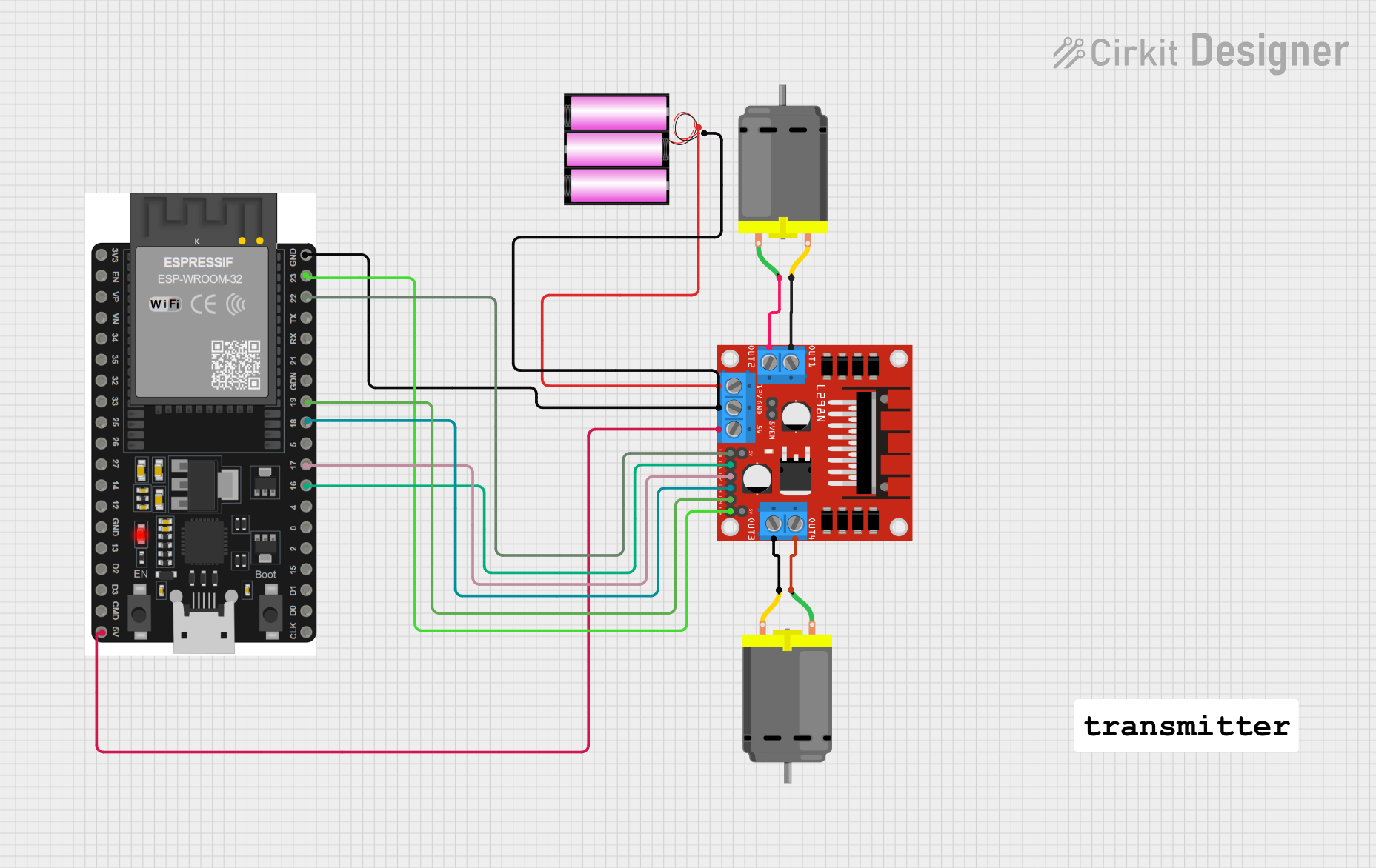
Circuit Documentation
Summary
This circuit is designed to control two DC motors using an L298N motor driver module, powered by a 12V battery, and controlled by an ESP32 microcontroller. The ESP32 is programmed to initialize WiFi and print the MAC address to the serial monitor.
Component List
L298N DC Motor Driver
- Description: A dual H-bridge motor driver that allows control of the speed and direction of two DC motors.
- Pins: OUT1, OUT2, 12V, GND, 5V, OUT3, OUT4, 5V-ENA-JMP-I, 5V-ENA-JMP-O, +5V-J1, +5V-J2, ENA, IN1, IN2, IN3, IN4, ENB
Battery 12V
- Description: A 12V battery used to power the motor driver and the motors.
- Pins: +, -
ESP32 38 PINS
- Description: A microcontroller with built-in WiFi and Bluetooth capabilities.
- Pins: GND, 23, 22/SCL, 1, 2, 21/SDA, 19, 18, 5, 17/TX2, 16/RX2, 4, 0, 15, D1, D0, CLK, 3V3, EN, VP, VN, 34, 35, 32, 33, 25, 26, 27, 14, 12, 13, D2, D3, 11, 5V/VIN
DC Motor (Motor 1)
- Description: A DC motor controlled by the L298N motor driver.
- Pins: pin 1, pin 2
DC Motor (Motor 2)
- Description: Another DC motor controlled by the L298N motor driver.
- Pins: pin 1, pin 2
Wiring Details
L298N DC Motor Driver
- OUT1 connected to pin 2 of DC Motor (Motor 2)
- OUT2 connected to pin 1 of DC Motor (Motor 2)
- 12V connected to + of Battery 12V
- GND connected to - of Battery 12V and GND of ESP32 38 PINS
- 5V connected to 5V/VIN of ESP32 38 PINS
- OUT3 connected to pin 2 of DC Motor (Motor 1)
- OUT4 connected to pin 1 of DC Motor (Motor 1)
- ENA connected to 22/SCL of ESP32 38 PINS
- IN1 connected to 16/RX2 of ESP32 38 PINS
- IN2 connected to 17/TX2 of ESP32 38 PINS
- IN3 connected to 18 of ESP32 38 PINS
- IN4 connected to 19 of ESP32 38 PINS
- ENB connected to 23 of ESP32 38 PINS
Battery 12V
- + connected to 12V of L298N DC Motor Driver
- - connected to GND of L298N DC Motor Driver and GND of ESP32 38 PINS
ESP32 38 PINS
- GND connected to - of Battery 12V and GND of L298N DC Motor Driver
- 5V/VIN connected to 5V of L298N DC Motor Driver
- 22/SCL connected to ENA of L298N DC Motor Driver
- 16/RX2 connected to IN1 of L298N DC Motor Driver
- 17/TX2 connected to IN2 of L298N DC Motor Driver
- 18 connected to IN3 of L298N DC Motor Driver
- 19 connected to IN4 of L298N DC Motor Driver
- 23 connected to ENB of L298N DC Motor Driver
DC Motor (Motor 1)
- pin 1 connected to OUT4 of L298N DC Motor Driver
- pin 2 connected to OUT3 of L298N DC Motor Driver
DC Motor (Motor 2)
- pin 1 connected to OUT2 of L298N DC Motor Driver
- pin 2 connected to OUT1 of L298N DC Motor Driver
Code Documentation
ESP32 Code
#include "WiFi.h"

void setup()
{
  Serial.begin(115200);
  WiFi.mode(WIFI_MODE_STA);
  Serial.println(WiFi.macAddress());
}

void loop()
{

}
- Description: This code initializes the ESP32, sets it to station mode, and prints the MAC address to the serial monitor. The loop function is empty and does not perform any operations.