
Arduino Mega 2560 Controlled Multi-Servo Robotic System with LED Indicator
View and Edit Project In Cirkit Designer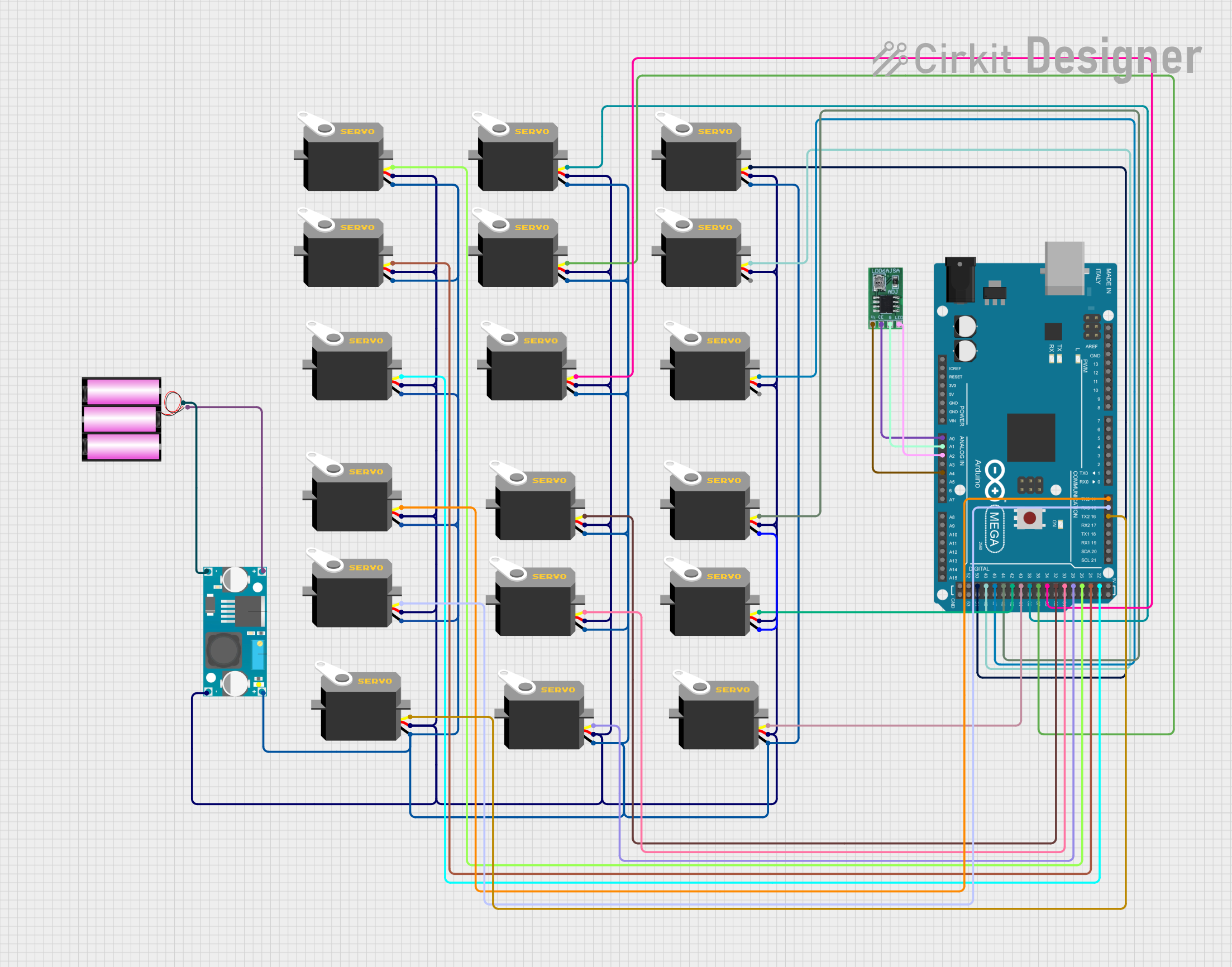
Circuit Documentation
Summary
This circuit involves an Arduino Mega 2560 microcontroller connected to multiple servos and an LD06AJSA LED component. The circuit is powered by a 12V battery through a power supply. The Arduino Mega 2560 controls the servos and the LED component, with each servo connected to a specific digital pin on the Arduino. The power supply ensures that all components receive the necessary voltage and current.
Component List
Arduino Mega 2560
- Description: A microcontroller board based on the ATmega2560.
- Pins: IOREF, RESET, 3V3, 5V, GND, VIN, A0-A15, D0-D53, AREF, SDA, SCL
Servo
- Description: A servo motor used for precise control of angular position.
- Pins: gnd, vcc, pulse
LD06AJSA
- Description: An LED component.
- Pins: V1, CE, G, LED
Battery 12V
- Description: A 12V battery used to power the circuit.
- Pins: +, -
Power Supply
- Description: A power supply unit to regulate voltage and current.
- Pins: IN +, IN -, OUT +, OUT -
Wiring Details
Arduino Mega 2560
- A0: Connected to CE of LD06AJSA
- A1: Connected to G of LD06AJSA
- A2: Connected to LED of LD06AJSA
- A4: Connected to V1 of LD06AJSA
- D16 PWM/TX2: Connected to pulse of Servo
- D15/RX3: Connected to pulse of Servo
- D14/TX3: Connected to pulse of Servo
- D50: Connected to pulse of Servo
- D48: Connected to pulse of Servo
- D46: Connected to pulse of Servo
- D44: Connected to pulse of Servo
- D42: Connected to pulse of Servo
- D40: Connected to pulse of Servo
- D38: Connected to pulse of Servo
- D36: Connected to pulse of Servo
- D34: Connected to pulse of Servo
- D32: Connected to pulse of Servo
- D30: Connected to pulse of Servo
- D28: Connected to pulse of Servo
- D26: Connected to pulse of Servo
- D24: Connected to pulse of Servo
- D22: Connected to pulse of Servo
Servo
- gnd: Connected to OUT + of Power Supply
- vcc: Connected to OUT - of Power Supply
- pulse: Connected to various digital pins on Arduino Mega 2560
LD06AJSA
- CE: Connected to A0 of Arduino Mega 2560
- G: Connected to A1 of Arduino Mega 2560
- LED: Connected to A2 of Arduino Mega 2560
- V1: Connected to A4 of Arduino Mega 2560
Battery 12V
- +: Connected to IN - of Power Supply
- -: Connected to IN + of Power Supply
Power Supply
- IN +: Connected to - of Battery 12V
- IN -: Connected to + of Battery 12V
- OUT +: Connected to gnd of multiple Servos
- OUT -: Connected to vcc of multiple Servos
Code Documentation
Arduino Mega 2560 Code
void setup() {
  // put your setup code here, to run once:

}

void loop() {
  // put your main code here, to run repeatedly:

}
This code is a basic template for the Arduino Mega 2560. The setup() function is used to initialize any settings or configurations, and the loop() function contains the main code that runs repeatedly. Currently, both functions are empty and need to be filled with the appropriate logic to control the servos and the LED component.