
Circuit Documentation
Summary
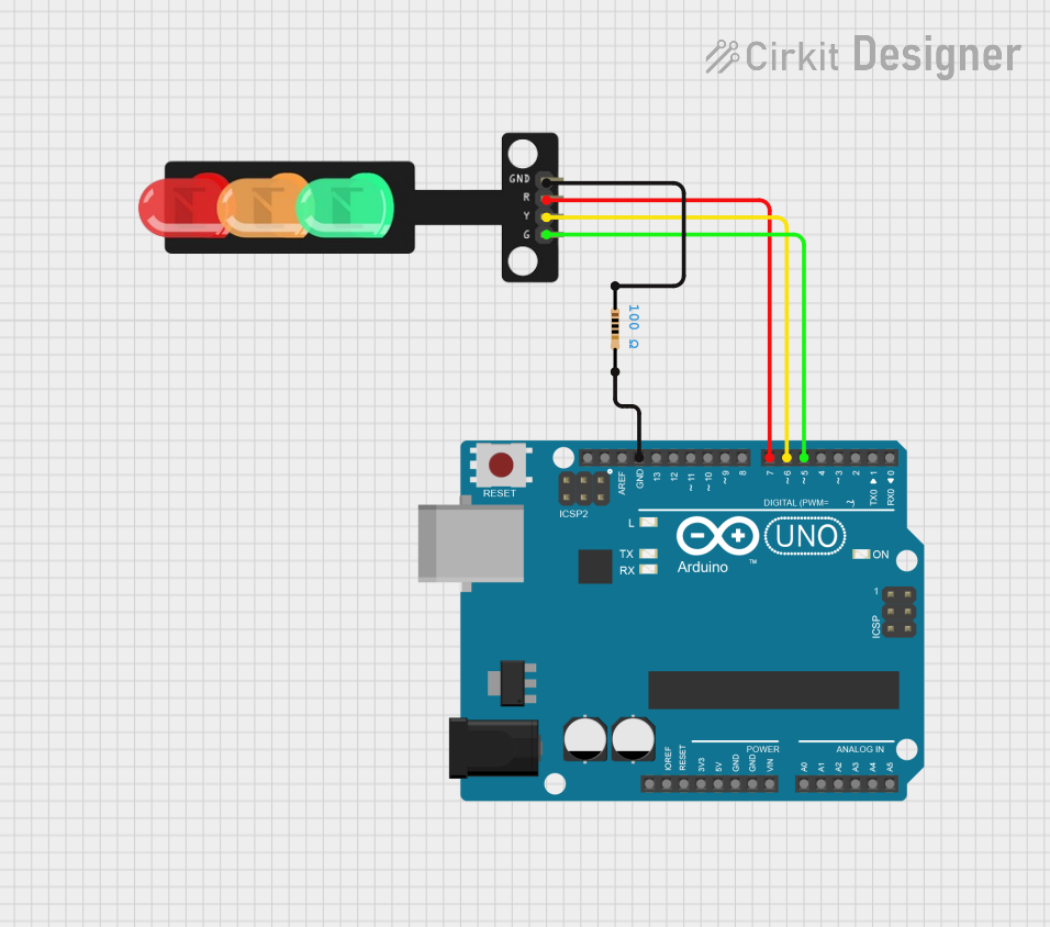
The circuit in question is designed to simulate a traffic light system using an Arduino UNO microcontroller and a traffic light module with three LEDs (Red, Yellow, Green). The system cycles through the traffic light sequence by turning on the red, yellow, and green LEDs in a timed pattern. A resistor is included in the circuit to provide a ground path for the traffic light module.
Component List
Arduino UNO
- Description: A microcontroller board based on the ATmega328P.
- Pins Used:
GND: Ground connection.D7: Digital pin connected to the Red LED of the traffic light.D6: Digital pin connected to the Yellow LED of the traffic light.D5: Digital pin connected to the Green LED of the traffic light.
Traffic Light
- Description: A module with three LEDs representing a traffic light.
- Pins Used:
Red: Connected to the Red LED.Yellow: Connected to the Yellow LED.Green: Connected to the Green LED.GND: Ground connection.
Resistor
- Description: A passive two-terminal electrical component that implements electrical resistance as a circuit element.
- Resistance: 100 Ohms.
- Pins Used:
pin1: Connected to the traffic light's ground.pin2: Connected to the Arduino's ground.
Wiring Details
Arduino UNO
GNDconnected to one end of the Resistor (100 Ohms).D7connected to the Red LED of the Traffic Light.D6connected to the Yellow LED of the Traffic Light.D5connected to the Green LED of the Traffic Light.
Traffic Light
Redconnected to Arduino UNO pinD7.Yellowconnected to Arduino UNO pinD6.Greenconnected to Arduino UNO pinD5.GNDconnected to the other end of the Resistor (100 Ohms).
Resistor
pin1connected to the Traffic LightGND.pin2connected to the Arduino UNOGND.
Documented Code
// sketch.ino
void setup() {
  pinMode(7, OUTPUT); // Red LED
  pinMode(6, OUTPUT); // Yellow LED
  pinMode(5, OUTPUT); // Green LED
}

void loop() {
  // Red light on, Yellow and Green off
  digitalWrite(7, HIGH);
  digitalWrite(6, LOW);
  digitalWrite(5, LOW);
  delay(5000); // Wait for 5 seconds

  // Yellow light on, Red and Green off
  digitalWrite(7, LOW);
  digitalWrite(6, HIGH);
  digitalWrite(5, LOW);
  delay(5000); // Wait for 5 seconds

  // Green light on, Red and Yellow off
  digitalWrite(7, LOW);
  digitalWrite(6, LOW);
  digitalWrite(5, HIGH);
  delay(5000); // Wait for 5 seconds
}
This code is designed to run on the Arduino UNO microcontroller. It initializes the digital pins 7, 6, and 5 as outputs in the setup() function. The loop() function then controls the traffic light sequence by turning on the red, yellow, and green LEDs in succession, each for a duration of 5 seconds.