
ESP8266-Based LED Control System with Potentiometer and Toggle Switch
View and Edit Project In Cirkit Designer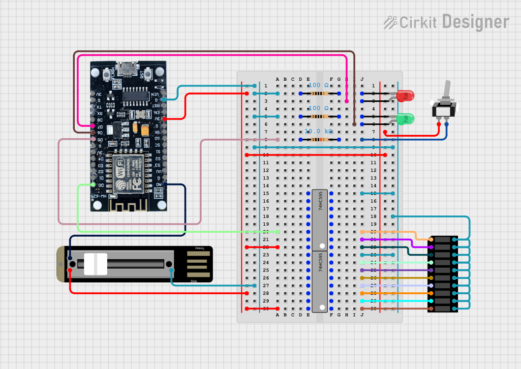
Circuit Documentation
Summary
This circuit is designed to control a red and green LED using a toggle switch and an LED bar using a potentiometer. The circuit utilizes an ESP8266 microcontroller to manage the LEDs and the LED bar. The red LED is connected to pin D7, the green LED to pin D6, and the potentiometer to pin A0. The LED bar is controlled via pins D4 (DI) and D3 (DCKI).
Component List
ESP8266
- Description: A Wi-Fi microcontroller used to control the LEDs and the LED bar.
- Pins: 3V, G, D8, D7, D6, D5, D4, D3, D2, D1, D0, A0, S3, S2, S1, SC, S0, SK, EN, VIN, RST, VU
Toggle Switch SPST
- Description: A single-pole single-throw switch used to toggle between the red and green LEDs.
- Pins: L1, COM
Adafruit Slide Trinkey
- Description: A small board with a potentiometer and touch sensor.
- Pins: 3.3V, POTENTIOMETER, GND, TOUCH
Resistor (100 Ohms)
- Description: Resistors used to limit current to the LEDs.
- Pins: pin1, pin2
Resistor (10k Ohms)
- Description: A resistor used in the circuit.
- Pins: pin1, pin2
LED: Two Pin (Red)
- Description: A red LED.
- Pins: cathode, anode
LED: Two Pin (Green)
- Description: A green LED.
- Pins: cathode, anode
Bar Graph (Wokwi Compatible)
- Description: An LED bar graph display.
- Pins: A1, A2, A3, A4, A5, A6, A7, A8, A9, A10, C8, C9, C10, C7, C6, C5, C4, C3, C2, C1
74HC595
- Description: A shift register used to control the LED bar.
- Pins: Q1, Q2, Q3, Q4, Q5, Q6, Q7, GND, VCC, Q0, DS (DATA), OE (Enable), ST_CP (RCLK), SH_CP (SRCLK), MR (SRCLR), Q7' (QH)
Wiring Details
ESP8266
- 3V: Connected to VCC of both 74HC595 shift registers and 3.3V of Adafruit Slide Trinkey.
- G: Connected to pin1 of two 100 Ohm resistors, GND of Adafruit Slide Trinkey, GND of both 74HC595 shift registers, and C1 to C10 of Bar Graph.
- D7: Connected to the anode of the red LED.
- D6: Connected to the anode of the green LED.
- D5: Connected to pin1 of the 10k Ohm resistor.
- D0: Connected to DS (DATA) of the first 74HC595 shift register.
- A0: Connected to the POTENTIOMETER of Adafruit Slide Trinkey.
Toggle Switch SPST
- L1: Connected to 3V of ESP8266.
- COM: Connected to pin2 of the 10k Ohm resistor.
Adafruit Slide Trinkey
- 3.3V: Connected to 3V of ESP8266.
- POTENTIOMETER: Connected to A0 of ESP8266.
- GND: Connected to G of ESP8266.
Resistor (100 Ohms)
- pin1: Connected to G of ESP8266.
- pin2: Connected to the cathode of the red LED.
Resistor (100 Ohms)
- pin1: Connected to G of ESP8266.
- pin2: Connected to the cathode of the green LED.
Resistor (10k Ohms)
- pin1: Connected to D5 of ESP8266.
- pin2: Connected to COM of Toggle Switch SPST.
LED: Two Pin (Red)
- anode: Connected to D7 of ESP8266.
- cathode: Connected to pin2 of the 100 Ohm resistor.
LED: Two Pin (Green)
- anode: Connected to D6 of ESP8266.
- cathode: Connected to pin2 of the 100 Ohm resistor.
Bar Graph (Wokwi Compatible)
- A1: Connected to Q3 of the first 74HC595 shift register.
- A2: Connected to Q2 of the first 74HC595 shift register.
- A3: Connected to Q1 of the first 74HC595 shift register.
- A4: Connected to Q7 of the second 74HC595 shift register.
- A5: Connected to Q6 of the second 74HC595 shift register.
- A6: Connected to Q5 of the second 74HC595 shift register.
- A7: Connected to Q4 of the second 74HC595 shift register.
- A8: Connected to Q3 of the second 74HC595 shift register.
- A9: Connected to Q2 of the second 74HC595 shift register.
- A10: Connected to Q1 of the second 74HC595 shift register.
- C1 to C10: Connected to G of ESP8266.
74HC595 (First)
- DS (DATA): Connected to D0 of ESP8266.
- GND: Connected to G of ESP8266.
- VCC: Connected to 3V of ESP8266.
- Q1: Connected to A3 of Bar Graph.
- Q2: Connected to A2 of Bar Graph.
- Q3: Connected to A1 of Bar Graph.
74HC595 (Second)
- GND: Connected to G of ESP8266.
- VCC: Connected to 3V of ESP8266.
- Q1: Connected to A10 of Bar Graph.
- Q2: Connected to A9 of Bar Graph.
- Q3: Connected to A8 of Bar Graph.
- Q4: Connected to A7 of Bar Graph.
- Q5: Connected to A6 of Bar Graph.
- Q6: Connected to A5 of Bar Graph.
- Q7: Connected to A4 of Bar Graph.
Code Documentation
/*
 * This Arduino Sketch controls a red and green LED using a toggle switch and
 * an LED bar using a potentiometer. The red LED is connected to pin D7, the
 * green LED to pin D6, and the potentiometer to pin A0. The LED bar is
 * controlled via pins D4 (DI) and D3 (DCKI).
 */

// Pin definitions
const int redLEDPin = D7;
const int greenLEDPin = D6;
const int toggleSwitchPin = D5;
const int potPin = A0;
const int ledBarDIPin = D4;
const int ledBarDCKIPin = D3;

void setup() {
  // Initialize pins
  pinMode(redLEDPin, OUTPUT);
  pinMode(greenLEDPin, OUTPUT);
  pinMode(toggleSwitchPin, INPUT);
  pinMode(ledBarDIPin, OUTPUT);
  pinMode(ledBarDCKIPin, OUTPUT);
}

void loop() {
  // Read the state of the toggle switch
  int toggleState = digitalRead(toggleSwitchPin);

  // Control the LEDs based on the toggle switch state
  if (toggleState == HIGH) {
    digitalWrite(redLEDPin, HIGH);
    digitalWrite(greenLEDPin, LOW);
  } else {
    digitalWrite(redLEDPin, LOW);
    digitalWrite(greenLEDPin, HIGH);
  }

  // Read the potentiometer value
  int potValue = analogRead(potPin);

  // Map the potentiometer value to a range suitable for the LED bar
  int ledBarValue = map(potValue, 0, 1023, 0, 255);

  // Control the LED bar
  analogWrite(ledBarDIPin, ledBarValue);
  analogWrite(ledBarDCKIPin, ledBarValue);

  // Small delay to stabilize readings
  delay(10);
}
This code initializes the pins for the red and green LEDs, the toggle switch, and the LED bar. In the loop function, it reads the state of the toggle switch to control the red and green LEDs. It also reads the potentiometer value and maps it to control the LED bar.