
Circuit Documentation
Summary
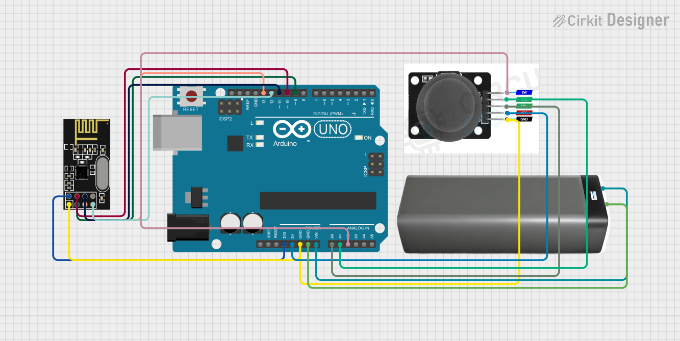
This circuit integrates an NRF24L01 wireless transceiver module with an Arduino UNO microcontroller board, a joystick module, and a battery pack to provide power. The NRF24L01 module enables wireless communication, while the joystick module allows for user input. The Arduino UNO serves as the central processing unit, interfacing with both the NRF24L01 and joystick module. The battery pack supplies the necessary power to the Arduino, which in turn powers the other components.
Component List
NRF24L01 Wireless Transceiver Module
- Description: A 2.4GHz wireless transceiver module.
- Purpose: Enables wireless communication for the circuit.
- Pins: IRQ (not used), MOSI, CSN, VCC (3V), GND, CE, SCK, MISO.
Joystick Module
- Description: An input device with two axes of control and a pushbutton.
- Purpose: Provides user input to control the circuit's functionality.
- Pins: SW, VRY, VRX, VCC, GND.
Battery Pack
- Description: A power source for the circuit.
- Purpose: Supplies electrical power to the Arduino UNO and, through it, to other components.
- Pins: +, -.
Arduino UNO
- Description: A microcontroller board based on the ATmega328P.
- Purpose: Acts as the central processing unit, controlling the NRF24L01 module and reading inputs from the joystick module.
- Pins: UNUSED, IOREF, Reset, 3.3V, 5V, GND, Vin, A0-A5, SCL, SDA, AREF, D0-D13.
Wiring Details
NRF24L01 Wireless Transceiver Module
- MOSI connected to Arduino UNO D11
- CSN connected to Arduino UNO D10
- VCC (3V) connected to Arduino UNO 3.3V
- GND connected to Arduino UNO GND
- CE connected to Arduino UNO D9
- SCK connected to Arduino UNO D13
- MISO connected to Arduino UNO D12
Joystick Module
- SW connected to Arduino UNO A2
- VRY connected to Arduino UNO A1
- VRX connected to Arduino UNO A0
- VCC connected to Arduino UNO 5V
- GND connected to Arduino UNO GND
Battery Pack
-
- connected to Arduino UNO Vin
-
- connected to Arduino UNO GND
Documented Code
Arduino UNO Code (sketch.ino)
void setup() {
  // put your setup code here, to run once:

}

void loop() {
  // put your main code here, to run repeatedly:

}
Additional Notes
- The provided code is a template and does not include specific functionality. It needs to be populated with the logic for initializing the NRF24L01 module, reading the joystick inputs, and implementing the desired behavior.
- The IRQ pin of the NRF24L01 is not used in this circuit.
- The joystick's SW pin is used for the pushbutton feature, which can be programmed to trigger events when pressed.
- The battery pack should provide a suitable voltage for the Arduino UNO's Vin pin, typically between 7V to 12V.