
Arduino Nano-Based Wireless Control System with NRF24L01 and I2C LCD
View and Edit Project In Cirkit Designer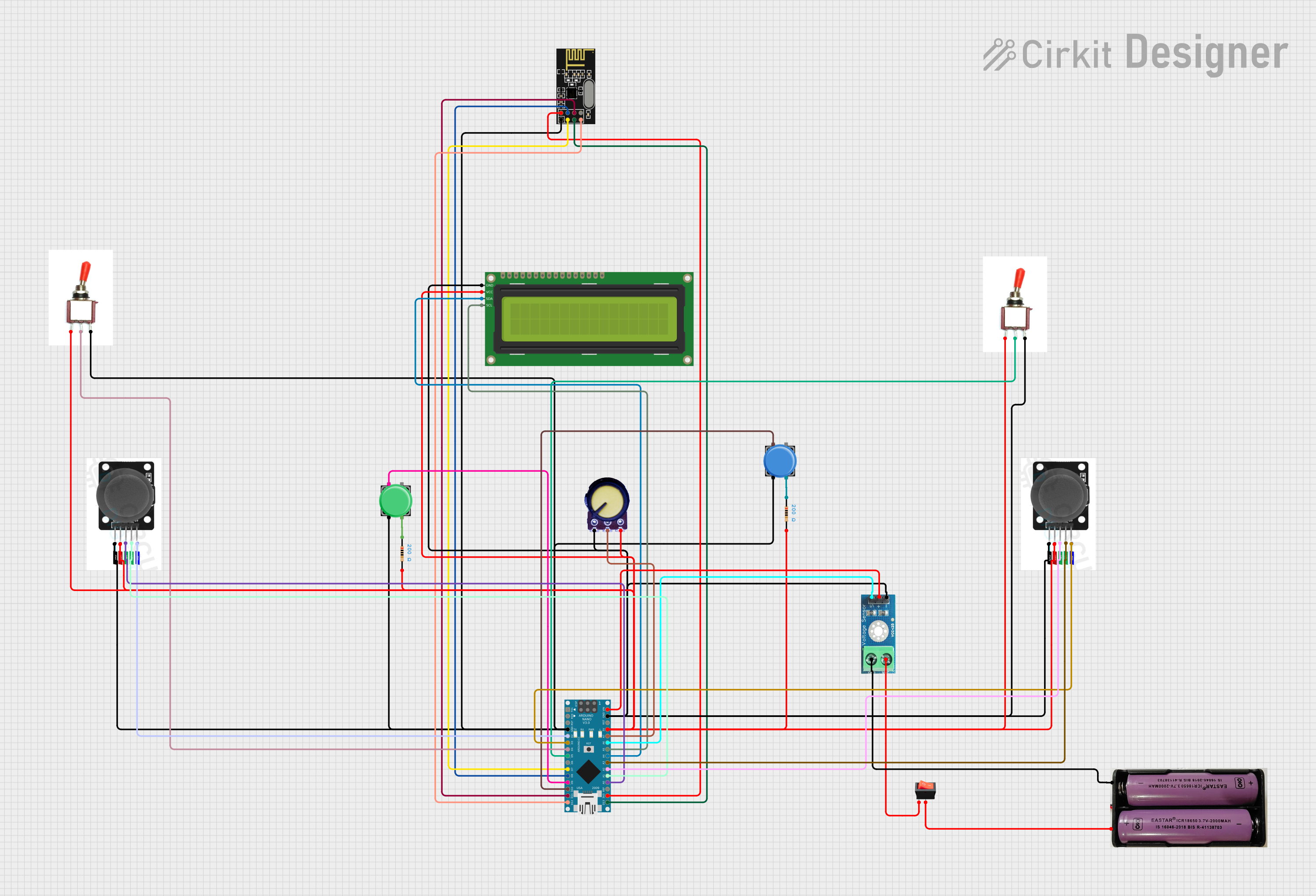
Circuit Documentation
Summary
This document provides a detailed overview of a circuit that includes an Arduino Nano microcontroller, various input devices (pushbuttons, toggle switches, joystick modules), an NRF24L01 wireless module, a 16x2 I2C LCD, a potentiometer, a voltage sensor, and a power source. The circuit is designed to interface these components with the Arduino Nano for various control and monitoring purposes.
Component List
Arduino Nano
- Description: A small, complete, and breadboard-friendly board based on the ATmega328P.
- Pins: D1/TX, D0/RX, RESET, GND, D2, D3, D4, D5, D6, D7, D8, D9, D10, D11/MOSI, D12/MISO, VIN, 5V, A7, A6, A5, A4, A3, A2, A1, A0, AREF, 3V3, D13/SCK
7.4v Battery
- Description: A 7.4V power source.
- Pins: +, -
16x2 I2C LCD
- Description: A 16x2 character LCD with I2C interface.
- Pins: GND, VCC, SDA, SCL
Pushbutton
- Description: A simple pushbutton switch.
- Pins: Pin 2, Pin 1, Pin 3, Pin 4
Potentiometer
- Description: A variable resistor used to adjust voltage.
- Pins: GND, Output, VCC
Toggle Switch
- Description: A switch that can toggle between two states.
- Pins: Vcc, Sig, Gnd
Joystick Module
- Description: A joystick module with X and Y axis and a switch.
- Pins: SW, VRY, VRX, VCC, GND
Rocker Switch
- Description: A switch that rocks back and forth to open or close a circuit.
- Pins: output, input
NRF24L01
- Description: A wireless transceiver module.
- Pins: IRQ (not used), MOSI, CSN, VCC (3V), GND, CE, SCK, MISO
Resistor
- Description: A 200 Ohm resistor.
- Pins: pin1, pin2
Voltage Sensor DC 25V
- Description: A sensor to measure DC voltage up to 25V.
- Pins: +, -, output, gnd, vcc
Wiring Details
Arduino Nano
- GND: Connected to GND of Pushbutton, Joystick module, Toggle Switch, NRF24L01, 16x2 I2C LCD, Voltage Sensor, Potentiometer, Joystick module
- D2: Connected to SW of Joystick module
- D3: Connected to SW of Joystick module
- D4: Connected to Sig of Toggle Switch
- D5: Connected to Sig of Toggle Switch
- D7: Connected to CE of NRF24L01
- D8: Connected to CSN of NRF24L01
- D9: Connected to Pin 1 of Pushbutton
- D10: Connected to Pin 1 of Pushbutton
- D11/MOSI: Connected to MOSI of NRF24L01
- D12/MISO: Connected to MISO of NRF24L01
- VIN: Connected to + of Voltage Sensor
- 5V: Connected to VCC of 16x2 I2C LCD, VCC of Joystick module, Vcc of Toggle Switch, VCC of Potentiometer, VCC of Joystick module
- A7: Connected to Output of Potentiometer
- A6: Connected to output of Voltage Sensor
- A5: Connected to SCL of 16x2 I2C LCD
- A4: Connected to SDA of 16x2 I2C LCD
- A3: Connected to VRY of Joystick module
- A2: Connected to VRX of Joystick module
- A1: Connected to VRY of Joystick module
- A0: Connected to VRX of Joystick module
- 3V3: Connected to VCC (3V) of NRF24L01
- D13/SCK: Connected to SCK of NRF24L01
7.4v Battery
- +: Connected to output of Rocker Switch
- -: Connected to gnd of Voltage Sensor
16x2 I2C LCD
- GND: Connected to Gnd of Toggle Switch, GND of Arduino Nano, - of Voltage Sensor, GND of Potentiometer, GND of Joystick module
- VCC: Connected to pin2 of Resistor, VCC of Joystick module, Vcc of Toggle Switch, pin2 of Resistor, 5V of Arduino Nano, Vcc of Toggle Switch, VCC of Potentiometer, VCC of Joystick module
- SDA: Connected to A4 of Arduino Nano
- SCL: Connected to A5 of Arduino Nano
Pushbutton
- Pin 2: Connected to Pin 2 of Pushbutton, GND of Joystick module, GND of Arduino Nano, Gnd of Toggle Switch, GND of NRF24L01
- Pin 1: Connected to D9 of Arduino Nano
- Pin 1: Connected to D10 of Arduino Nano
- Pin 4: Connected to pin1 of Resistor
- Pin 4: Connected to pin1 of Resistor
Potentiometer
- GND: Connected to GND of Arduino Nano
- Output: Connected to A7 of Arduino Nano
- VCC: Connected to 5V of Arduino Nano
Toggle Switch
- Vcc: Connected to VCC of 16x2 I2C LCD, pin2 of Resistor, VCC of Joystick module, Vcc of Toggle Switch, pin2 of Resistor, 5V of Arduino Nano, Vcc of Toggle Switch, VCC of Potentiometer, VCC of Joystick module
- Sig: Connected to D4 of Arduino Nano
- Gnd: Connected to GND of Arduino Nano
Joystick Module
- SW: Connected to D2 of Arduino Nano
- VRY: Connected to A1 of Arduino Nano
- VRX: Connected to A0 of Arduino Nano
- VCC: Connected to 5V of Arduino Nano
- GND: Connected to GND of Arduino Nano
Rocker Switch
- output: Connected to + of 7.4v Battery
- input: Connected to vcc of Voltage Sensor
NRF24L01
- GND: Connected to GND of Arduino Nano
- CE: Connected to D7 of Arduino Nano
- CSN: Connected to D8 of Arduino Nano
- MOSI: Connected to D11/MOSI of Arduino Nano
- MISO: Connected to D12/MISO of Arduino Nano
- VCC (3V): Connected to 3V3 of Arduino Nano
- SCK: Connected to D13/SCK of Arduino Nano
Resistor
- pin1: Connected to Pin 4 of Pushbutton
- pin2: Connected to VCC of 16x2 I2C LCD
Voltage Sensor DC 25V
- +: Connected to VIN of Arduino Nano
- -: Connected to GND of 16x2 I2C LCD
- output: Connected to A6 of Arduino Nano
- gnd: Connected to - of 7.4v Battery
- vcc: Connected to input of Rocker Switch
Documented Code
Arduino Nano Code (sketch.ino)
void setup() {
  // put your setup code here, to run once:

}

void loop() {
  // put your main code here, to run repeatedly:

}
This concludes the documentation for the circuit. Each component and its connections have been detailed, and the code for the Arduino Nano has been provided.