ESP32-Based Multi-Sensor Health Monitoring System with Bluetooth Connectivity

Circuit Documentation
Summary
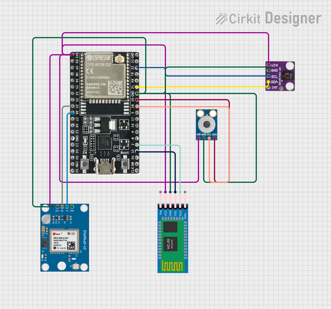
The circuit in question is designed to interface various sensor modules and a communication module with an ESP32 microcontroller. The sensors include a MAX30100 pulse oximeter and heart-rate sensor, an MLX90614 infrared thermometer, and a Neo 6M GPS module. Additionally, an HC-05 Bluetooth module is included for wireless communication. The ESP32 serves as the central processing unit, handling data from the sensors and managing communication through the Bluetooth module. Power distribution is unified across the components, and communication lines are established via I2C and serial interfaces.
Component List
MAX30100 Pulse Oximeter and Heart-Rate Sensor
- Pins: Vin, GND, SCL, SDA, INT
- Description: This sensor is used for measuring blood oxygen saturation and heart rate.
MLX90614 Infrared Thermometer
- Pins: SDA, SCL, GND, VIN
- Description: An infrared thermometer for non-contact temperature measurements.
HC-05 Bluetooth Module
- Pins: Key, VCC, GND, TXD, RXD, State
- Description: A Bluetooth module for wireless communication.
Neo 6M GPS Module
- Pins: GND, TX, RX, VCC
- Description: A GPS receiver module for obtaining geographical position data.
ESP32-WROOM-32UE Microcontroller
- Pins: 3v3, EN, VP, VN, 34, 35, 32, 33, 25, 26, 27, 14, 12, GND, 13, D2, D3, 5V, 23, 22, TX, RX, 21, 19, 18, 5, 17, 16, 4, 0, 2, 15, D1, D0, CKL
- Description: The main microcontroller unit that processes data and controls the circuit.
Wiring Details
MAX30100 Pulse Oximeter and Heart-Rate Sensor
- Vin: Connected to the power supply net.
- GND: Connected to the ground net.
- SCL: Connected to ESP32 pin 22 (I2C clock).
- SDA: Connected to ESP32 pin 21 (I2C data).
- INT: Not connected in the current configuration.
MLX90614 Infrared Thermometer
- VIN: Connected to the power supply net.
- GND: Connected to the ground net.
- SDA: Connected to ESP32 pin 19 (I2C data).
- SCL: Connected to ESP32 pin 18 (I2C clock).
HC-05 Bluetooth Module
- VCC: Connected to the power supply net.
- GND: Connected to the ground net.
- TXD: Connected to ESP32 pin 15 (UART receive).
- RXD: Connected to ESP32 pin 2 (UART transmit).
- Key, State: Not connected in the current configuration.
Neo 6M GPS Module
- VCC: Connected to the power supply net.
- GND: Connected to the ground net.
- TX: Connected to ESP32 pin 26 (UART receive).
- RX: Connected to ESP32 pin 25 (UART transmit).
ESP32-WROOM-32UE Microcontroller
- 3v3: Power supply for the microcontroller and connected sensors/modules.
- GND: Common ground for the microcontroller and connected sensors/modules.
- Pins 22, 21, 19, 18, 15, 2, 26, 25: Used for communication with sensors and modules.
- Other Pins: Not used in the current configuration or reserved for future expansion.
Documented Code
No code has been provided for the microcontrollers in the circuit. The code would typically include initialization and configuration of I2C and UART interfaces, data acquisition from the sensors, processing of sensor data, and handling Bluetooth communication with the HC-05 module.