Solar-Powered DC Motor Control with ATS and AC Backup

Circuit Documentation
Summary of the Circuit
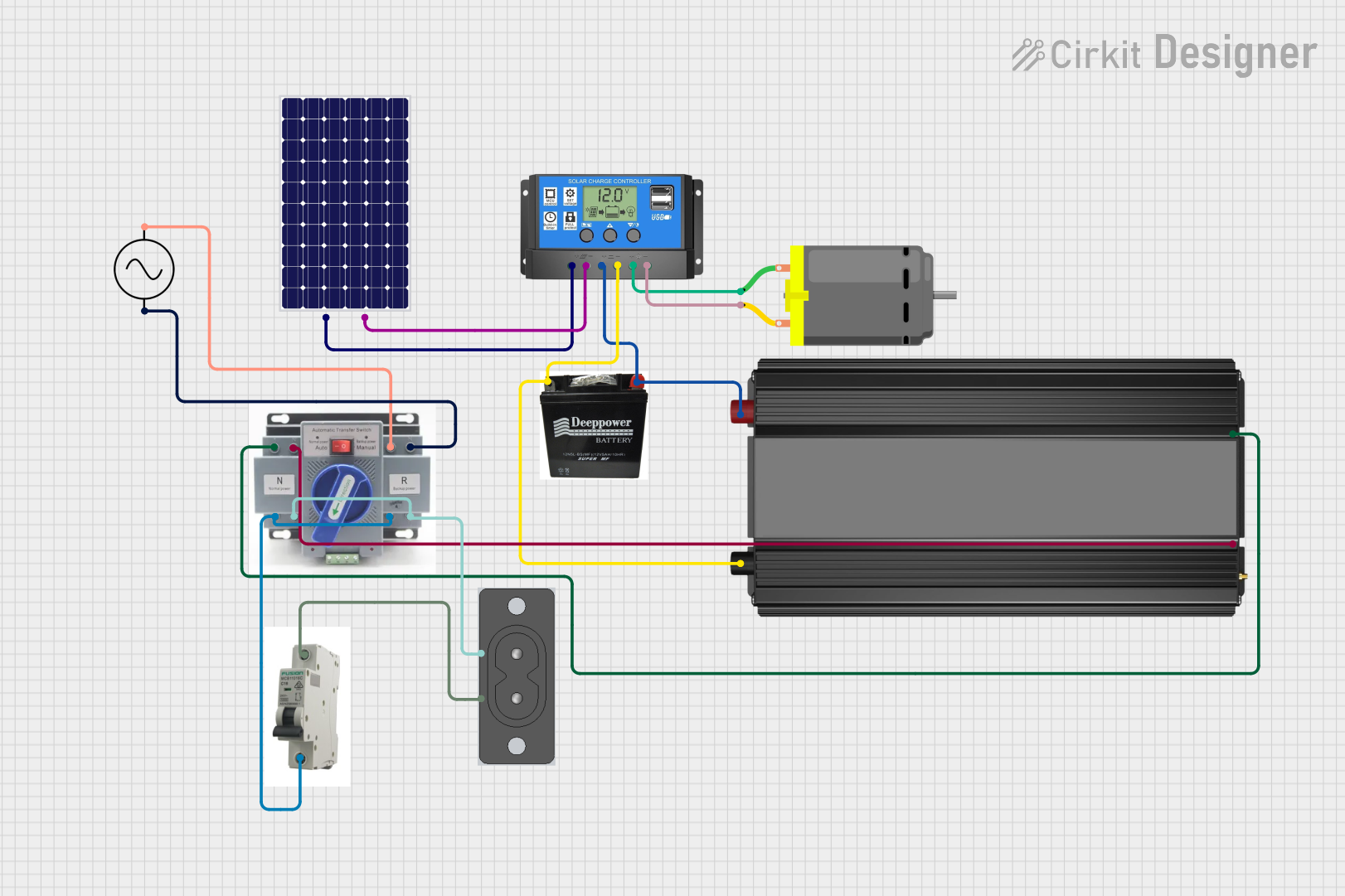
This circuit is designed to harness solar energy through a solar panel, manage the charging of a battery via a solar charge controller, and provide both DC and AC power outputs. The DC output is used to drive a DC motor, while the AC output is provided through a 2 Prong AC Socket, which is connected to an AC supply via an Automatic Transfer Switch (ATS) and a Miniature Circuit Breaker (MCB). The power inverter converts the DC power from the battery to AC power for the socket. The ATS ensures that the AC supply is used when solar power is insufficient.
Component List
Battery
A storage device for electrical energy, typically used to provide power to the circuit when solar energy is not available.
Solar Charge Controller
A device that regulates the voltage and current coming from the solar panels going to the battery. It ensures that the battery is charged properly and prevents overcharging.
Power Inverter
Converts DC power from the battery into AC power, which can be used by AC appliances.
ATS (Automatic Transfer Switch)
Automatically switches between the solar panel/battery system and the AC supply, ensuring continuous power supply to the load.
Solar Panel
A photovoltaic panel that converts sunlight into electrical energy, which is then used to charge the battery or power the load directly.
AC Supply
Represents the mains electricity supply, providing an alternative source of AC power to the circuit.
MCB (Miniature Circuit Breaker)
A safety device that automatically cuts off the electrical power in case of an overload or short circuit in the AC supply line.
2 Prong AC Socket
An interface for AC-powered devices to connect to the circuit's AC power output.
DC Motor
An electric motor that runs on direct current (DC) electricity, powered by the solar charge controller in this circuit.
Wiring Details
Battery
- Positive terminal connected to the Solar Charge Controller's "Battery +" pin.
- Negative terminal connected to the Solar Charge Controller's "Battery -" pin.
Solar Charge Controller
- "Solar Cell +" pin connected to the Solar Panel's "+" pin.
- "Solar Cell -" pin connected to the Solar Panel's "-" pin.
- "Battery +" and "Battery -" pins connected to the corresponding pins of the Battery.
- "Load +" pin connected to the DC Motor's "pin 1".
- "Load -" pin connected to the DC Motor's "pin 2".
Power Inverter
- "+" pin connected to the Solar Charge Controller's "Battery +" pin and the ATS's "+" pin.
- "-" pin connected to the Solar Charge Controller's "Battery -" pin and the ATS's "-" pin.
ATS (Automatic Transfer Switch)
- "+" and "-" pins connected to the corresponding pins of the Power Inverter.
- "+" pin also connected to the MCB's "IN" pin and the AC Supply's "+ve" pin.
- "-" pin also connected to the AC Supply's "-ve" pin.
- The ATS's "-" pin is connected to the 2 Prong AC Socket's "AC -" pin.
Solar Panel
- "+" pin connected to the Solar Charge Controller's "Solar Cell +" pin.
- "-" pin connected to the Solar Charge Controller's "Solar Cell -" pin.
AC Supply
- "+ve" pin connected to the ATS's "+" pin.
- "-ve" pin connected to the ATS's "-" pin.
MCB (Miniature Circuit Breaker)
- "IN" pin connected to the ATS's "+" pin.
- "OUT" pin connected to the 2 Prong AC Socket's "AC +" pin.
2 Prong AC Socket
- "AC +" pin connected to the MCB's "OUT" pin.
- "AC -" pin connected to the ATS's "-" pin.
DC Motor
- "pin 1" connected to the Solar Charge Controller's "Load +" pin.
- "pin 2" connected to the Solar Charge Controller's "Load -" pin.
Documented Code
There is no embedded code provided for any microcontrollers in this circuit. If any microcontrollers or programmable devices are added to the circuit in the future, the code will be documented in this section.