
Circuit Documentation
Summary
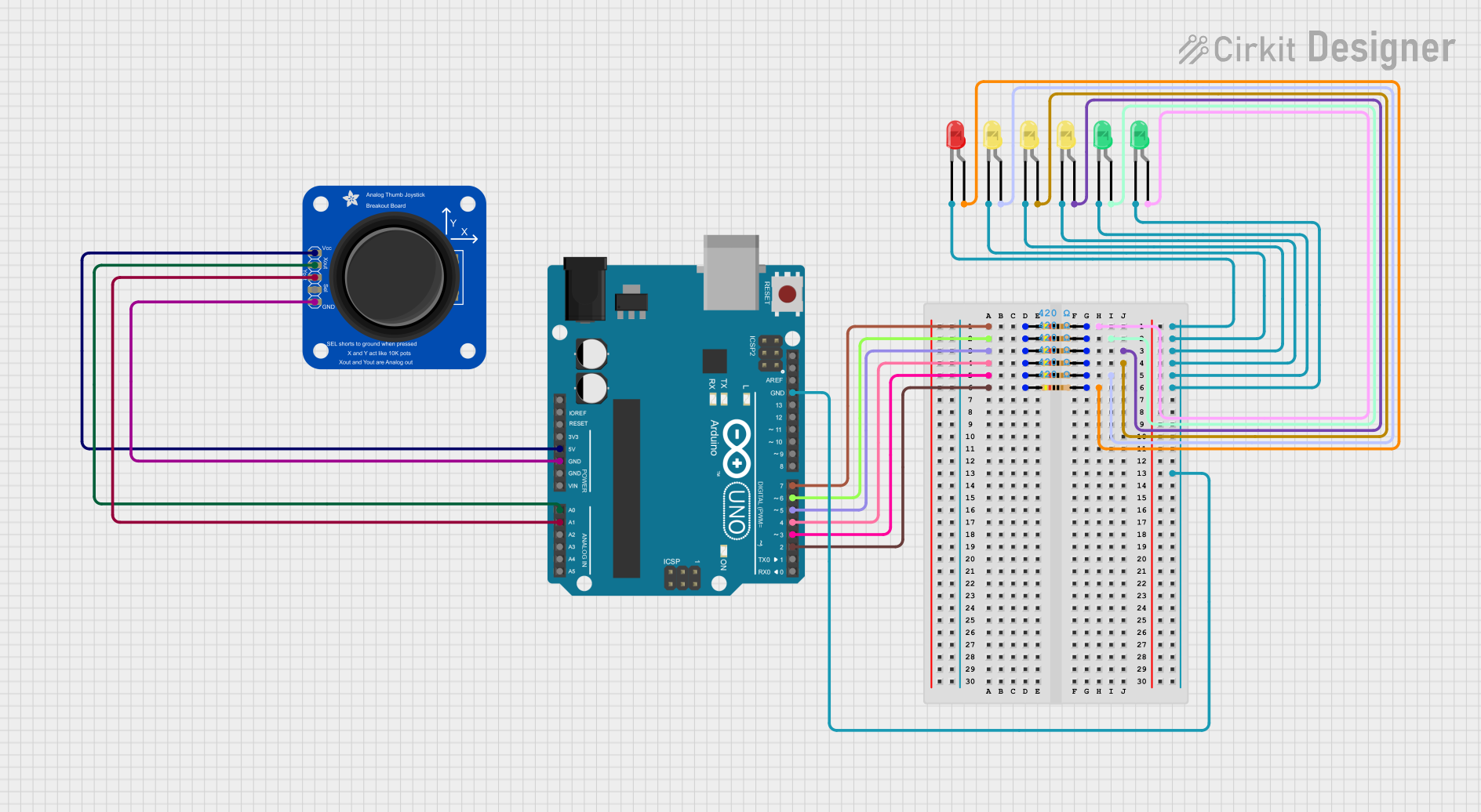
This circuit involves an Arduino UNO microcontroller interfaced with an Adafruit Analog 2-Axis Joystick and several LEDs (red, green, and yellow) through resistors. The joystick provides analog input to the Arduino, while the LEDs are controlled via digital output pins on the Arduino.
Component List
Adafruit Analog 2-Axis Joystick
- Pins: VCC, XOUT, YOUT, SWITCH, GND
- Description: An analog joystick that provides two-axis control and a switch button.
Arduino UNO
- Pins: UNUSED, IOREF, Reset, 3.3V, 5V, GND, Vin, A0, A1, A2, A3, A4, A5, SCL, SDA, AREF, D13, D12, D11, D10, D9, D8, D7, D6, D5, D4, D3, D2, D1, D0
- Description: A microcontroller board based on the ATmega328P.
LED: Two Pin (red)
- Pins: cathode, anode
- Description: A red LED.
LED: Two Pin (green)
- Pins: cathode, anode
- Description: A green LED.
LED: Two Pin (yellow)
- Pins: cathode, anode
- Description: A yellow LED.
Resistor
- Pins: pin1, pin2
- Description: A resistor with a resistance of 420 Ohms.
Wiring Details
Adafruit Analog 2-Axis Joystick
- VCC connected to 5V on Arduino UNO.
- XOUT connected to A0 on Arduino UNO.
- YOUT connected to A1 on Arduino UNO.
- GND connected to GND on Arduino UNO.
Arduino UNO
- D7 connected to pin1 of a Resistor.
- D6 connected to pin1 of a Resistor.
- D5 connected to pin1 of a Resistor.
- D4 connected to pin1 of a Resistor.
- D3 connected to pin1 of a Resistor.
- D2 connected to pin1 of a Resistor.
- GND connected to the cathodes of all LEDs.
LED: Two Pin (red)
- anode connected to pin2 of a Resistor.
- cathode connected to GND on Arduino UNO.
LED: Two Pin (green)
- anode connected to pin2 of a Resistor.
- cathode connected to GND on Arduino UNO.
LED: Two Pin (yellow)
- anode connected to pin2 of a Resistor.
- cathode connected to GND on Arduino UNO.
Resistor
- pin1 connected to D7 on Arduino UNO, pin2 connected to the anode of a green LED.
- pin1 connected to D6 on Arduino UNO, pin2 connected to the anode of a green LED.
- pin1 connected to D5 on Arduino UNO, pin2 connected to the anode of a yellow LED.
- pin1 connected to D4 on Arduino UNO, pin2 connected to the anode of a yellow LED.
- pin1 connected to D3 on Arduino UNO, pin2 connected to the anode of a yellow LED.
- pin1 connected to D2 on Arduino UNO, pin2 connected to the anode of a red LED.
Code Documentation
Arduino UNO Code
void setup() {
  // put your setup code here, to run once:

}

void loop() {
  // put your main code here, to run repeatedly:

}
This code is a basic template for the Arduino UNO. The setup() function is where you initialize your settings, and the loop() function is where the main code runs repeatedly. Currently, the code does not perform any specific actions.