
Arduino UNO-Based Scoreboard with Light Detection and LED Indicators
View and Edit Project In Cirkit Designer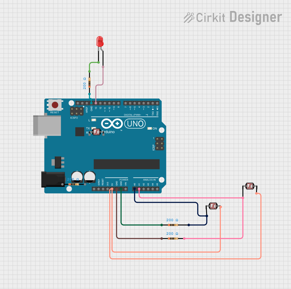
Circuit Documentation
Summary
The circuit is designed to function as a scoreboard system, utilizing two photocells (LDRs) to detect scores for two teams. When a score is detected, an LED for the corresponding team is illuminated. The Arduino UNO microcontroller reads analog inputs from the photocells and controls the LEDs based on the sensor values. The circuit includes resistors for current limiting and voltage division purposes.
Component List
Arduino UNO
- Microcontroller board based on the ATmega328P
- It has 14 digital input/output pins, 6 analog inputs, a 16 MHz quartz crystal, a USB connection, a power jack, an ICSP header, and a reset button.
Photocell (LDR)
- A light-dependent resistor whose resistance changes with light intensity
- Used to detect score events in the circuit
Resistor (200 Ohms)
- A passive two-terminal electrical component that implements electrical resistance as a circuit element
- Used for current limiting and voltage division
LED: Two Pin (red)
- A red light-emitting diode
- Used to indicate a score event for a team
Wiring Details
Arduino UNO
5Vpin is connected to thepin 1of both Photocells (LDR)GNDpin is connected to one side (pin1) of each 200 Ohm ResistorA0pin is connected to the junction betweenpin 0of Photocell 1 andpin2of a 200 Ohm ResistorA1pin is connected to the junction betweenpin 0of Photocell 2 andpin2of another 200 Ohm ResistorD13pin is connected to theanodeof the red LEDGNDpin is also connected to thecathodeof the red LED through a 200 Ohm Resistor
Photocell (LDR)
- One side (
pin 0) is connected to an analog input on the Arduino UNO (eitherA0orA1) - The other side (
pin 1) is connected to the5Vsupply on the Arduino UNO
Resistor (200 Ohms)
- One side (
pin1) is connected to theGNDon the Arduino UNO - The other side (
pin2) is connected to either a Photocell (LDR) or thecathodeof the red LED
LED: Two Pin (red)
Anodeis connected to theD13on the Arduino UNOCathodeis connected toGNDon the Arduino UNO through a 200 Ohm Resistor
Documented Code
/*
  Scoreboard Project

  This code reads analog inputs from two photocells (LDRs) connected to pins A0
  and A1. If the analog value of either photocell is below a threshold, it
  indicates a score by turning on an LED connected to pin D13 for team 1 or
  pin D12 for team 2. Otherwise, it turns off the respective LED and prints the
  sensor values to the Serial Monitor.
*/

// Pin definitions
const int photocellPin1 = A0;  // Photocell for team 1 connected to A0
const int photocellPin2 = A1;  // Photocell for team 2 connected to A1
const int ledPin1 = 13;        // LED for team 1 connected to D13
const int ledPin2 = 12;        // LED for team 2 connected to D12

// Threshold for detecting a score
const int threshold = 10;

void setup() {
  // Initialize serial communication at 9600 bits per second
  Serial.begin(9600);
  // Initialize the LED pins as outputs
  pinMode(ledPin1, OUTPUT);
  pinMode(ledPin2, OUTPUT);
}

void loop() {
  // Read the input on analog pins A0 and A1
  int sensorValue1 = analogRead(photocellPin1);
  int sensorValue2 = analogRead(photocellPin2);
  // Check if the sensor value for team 1 is below the threshold
  if (sensorValue1 < threshold) {
    Serial.println("Team 1 Scores!");
    digitalWrite(ledPin1, HIGH);  // Turn the LED on for team 1
    delay(1000);  // Delay for 1 second
  } else {
    digitalWrite(ledPin1, LOW);  // Turn the LED off for team 1
    Serial.print("Team 1: ");
    Serial.println(sensorValue1);  // Print the sensor value for team 1
  }
  // Check if the sensor value for team 2 is below the threshold
  if (sensorValue2 < threshold) {
    Serial.println("Team 2 Scores!");
    digitalWrite(ledPin2, HIGH);  // Turn the LED on for team 2
    delay(1000);  // Delay for 1 second
  } else {
    digitalWrite(ledPin2, LOW);  // Turn the LED off for team 2
    Serial.print("Team 2: ");
    Serial.println(sensorValue2);  // Print the sensor value for team 2
  }
  delay(1);  // Delay in between reads for stability
}
Filename: Scoreboard sketch 20241008.ino