
Wi-Fi Controlled Smart Home Security System with ESP8266 and Multiple Sensors
View and Edit Project In Cirkit Designer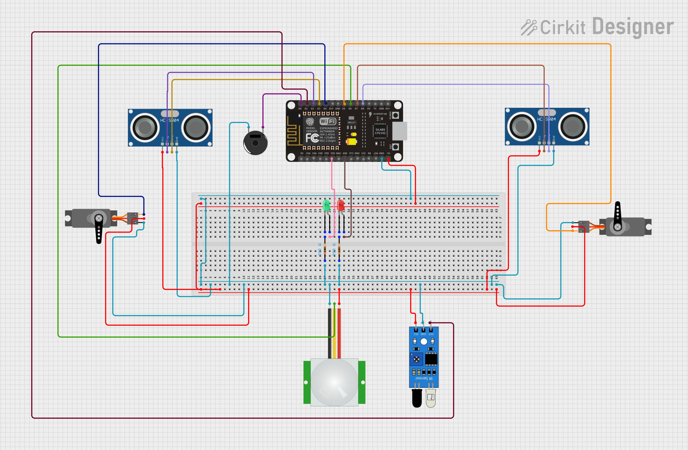
Circuit Documentation
Summary
This document provides a detailed overview of a circuit that includes various sensors, actuators, and an ESP8266 NodeMCU microcontroller. The circuit is designed to interface with multiple components such as ultrasonic sensors, PIR sensors, IR sensors, servos, LEDs, resistors, and a piezo buzzer. The ESP8266 NodeMCU serves as the central controller, managing inputs from sensors and controlling outputs to actuators.
Component List
HC-SR04 Ultrasonic Sensor
- Pins: VCC, TRIG, ECHO, GND
- Description: Measures distance by using ultrasonic waves.
- Purpose: Distance measurement.
PIR Sensor
- Pins: VDD, SIG, GND
- Description: Detects motion using passive infrared technology.
- Purpose: Motion detection.
Servo
- Pins: GND, VCC, PWM
- Description: A small motor with a feedback mechanism for precise control.
- Purpose: Actuation.
ESP8266 NodeMCU
- Pins: D0, D1, D2, D3, D4, 3V3, GND, D5, D6, D7, D8, RX, TX, A0, RSV, SD3, SD2, SD1, CMD, SD0, CLK, EN, RST, VIN
- Description: A low-cost Wi-Fi microcontroller.
- Purpose: Central controller.
LED: Two Pin (Red)
- Pins: Cathode, Anode
- Description: A red light-emitting diode.
- Purpose: Visual indicator.
LED: Two Pin (Green)
- Pins: Cathode, Anode
- Description: A green light-emitting diode.
- Purpose: Visual indicator.
Resistor
- Pins: Pin1, Pin2
- Description: A 200 Ohms resistor.
- Purpose: Current limiting.
IR Sensor
- Pins: Out, GND, VCC
- Description: Detects infrared light.
- Purpose: Object detection.
Piezo Buzzer
- Pins: Pin 1, Pin 2
- Description: Produces sound when an electric signal is applied.
- Purpose: Audible alert.
Wiring Details
HC-SR04 Ultrasonic Sensor
- VCC: Connected to VIN of ESP8266 NodeMCU.
- TRIG: Connected to D2 of ESP8266 NodeMCU.
- ECHO: Connected to D3 of ESP8266 NodeMCU.
- GND: Connected to GND (common ground).
PIR Sensor
- VDD: Connected to VIN of ESP8266 NodeMCU.
- SIG: Connected to D6 of ESP8266 NodeMCU.
- GND: Connected to GND (common ground).
Servo (Instance 1)
- GND: Connected to GND (common ground).
- VCC: Connected to VIN of ESP8266 NodeMCU.
- PWM: Connected to D4 of ESP8266 NodeMCU.
Servo (Instance 2)
- GND: Connected to GND (common ground).
- VCC: Connected to VIN of ESP8266 NodeMCU.
- PWM: Connected to D5 of ESP8266 NodeMCU.
ESP8266 NodeMCU
- VIN: Connected to VCC of various components.
- GND: Connected to GND (common ground).
- D0: Connected to Pin 1 of Piezo Buzzer.
- D1: Connected to Out of IR Sensor.
- D2: Connected to TRIG of HC-SR04 Ultrasonic Sensor (Instance 1).
- D3: Connected to ECHO of HC-SR04 Ultrasonic Sensor (Instance 1).
- D4: Connected to PWM of Servo (Instance 1).
- D5: Connected to PWM of Servo (Instance 2).
- D6: Connected to SIG of PIR Sensor.
- D7: Connected to TRIG of HC-SR04 Ultrasonic Sensor (Instance 2).
- D8: Connected to ECHO of HC-SR04 Ultrasonic Sensor (Instance 2).
- SD0: Connected to Anode of Red LED.
- SD1: Connected to Anode of Green LED.
LED: Two Pin (Red)
- Anode: Connected to SD0 of ESP8266 NodeMCU.
- Cathode: Connected to Pin2 of Resistor (Instance 2).
LED: Two Pin (Green)
- Anode: Connected to SD1 of ESP8266 NodeMCU.
- Cathode: Connected to Pin2 of Resistor (Instance 1).
Resistor (Instance 1)
- Pin1: Connected to GND (common ground).
- Pin2: Connected to Cathode of Green LED.
Resistor (Instance 2)
- Pin1: Connected to GND (common ground).
- Pin2: Connected to Cathode of Red LED.
IR Sensor
- Out: Connected to D1 of ESP8266 NodeMCU.
- GND: Connected to GND (common ground).
- VCC: Connected to VIN of ESP8266 NodeMCU.
Piezo Buzzer
- Pin 1: Connected to D0 of ESP8266 NodeMCU.
- Pin 2: Connected to GND (common ground).
Code
No code provided for this circuit.
This document provides a comprehensive overview of the circuit, including a summary, component list, wiring details, and code section. Each component is described, and its connections are detailed to ensure clarity and ease of understanding.