
Circuit Documentation
Summary
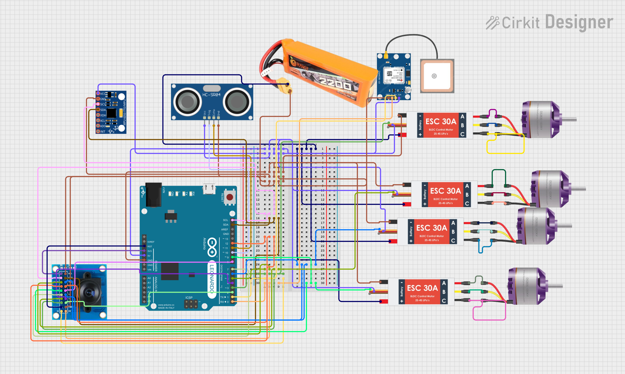
The circuit in question is designed to control a quadcopter with four brushless motors, each connected to an individual Electronic Speed Controller (ESC). The circuit includes an Arduino Leonardo microcontroller for processing and control, an MPU-6050 sensor for motion tracking, a GPS NEO 6M module for positioning, an HC-SR04 ultrasonic sensor for distance measurement, and an OV7725 camera module for visual data capture. The system is powered by a lipo battery, and the ESCs provide power distribution to the other components.
Component List
Brushless Motor
- Description: A type of electric motor that uses electronic commutation instead of mechanical brushes.
- Purpose: Provides thrust for the quadcopter.
Electronic Speed Controller (ESC)
- Description: An electronic circuit that controls the speed of an electric motor.
- Purpose: Regulates the power supplied to the brushless motors.
MPU-6050
- Description: A motion tracking device that contains a MEMS accelerometer and a MEMS gyro in a single chip.
- Purpose: Measures the quadcopter's acceleration and angular rate.
HC-SR04 Ultrasonic Sensor
- Description: An ultrasonic ranging module that provides 2 cm to 400 cm non-contact measurement functionality.
- Purpose: Measures the distance between the quadcopter and the ground or other objects.
OV7725 Camera Module
- Description: A small size, low voltage, single-chip VGA camera.
- Purpose: Captures visual data for image processing or navigation.
Arduino Leonardo (Rev3b)
- Description: A microcontroller board based on the ATmega32u4.
- Purpose: Acts as the central processing unit, controlling the ESCs, reading sensor data, and managing communication.
GPS NEO 6M
- Description: A compact GPS module with high tracking sensitivity.
- Purpose: Provides positioning data for the quadcopter.
Lipo Battery 2200mAh 30C
- Description: A rechargeable battery with high energy density.
- Purpose: Supplies power to the entire circuit.
Wiring Details
Brushless Motors
- Connected to the corresponding M1, M2, and M3 pins of each ESC.
Electronic Speed Controllers (ESCs)
- Battery VCC: Connected to the VCC of the lipo battery.
- Battery GND: Connected to the GND of the lipo battery and the GND of all other components.
- Signal: Connected to the respective PWM pins on the Arduino Leonardo for speed control.
- 5v out: Provides power to the Arduino Leonardo, MPU-6050, GPS NEO 6M, and HC-SR04 Ultrasonic Sensor.
MPU-6050
- VCC: Powered by the 5V output from an ESC.
- GND: Connected to the common ground.
- SCL: Connected to the SCL pin on the Arduino Leonardo.
- SDA: Connected to the SDA pin on the Arduino Leonardo.
HC-SR04 Ultrasonic Sensor
- VCC: Powered by the 5V output from an ESC.
- TRIG: Connected to pin D10 on the Arduino Leonardo.
- ECHO: Connected to pin D11 on the Arduino Leonardo.
- GND: Connected to the common ground.
OV7725 Camera Module
- 3V3: Powered by the 3.3V pin on the Arduino Leonardo.
- GND: Connected to the common ground.
- SIOC: Connected to the SCL pin on the Arduino Leonardo.
- SIOD: Connected to the SDA pin on the Arduino Leonardo.
- Various data pins: Connected to the corresponding digital pins on the Arduino Leonardo.
Arduino Leonardo (Rev3b)
- 5V: Receives power from an ESC's 5V output.
- GND: Connected to the common ground.
- Digital and Analog Pins: Connected to various components for control and data acquisition.
GPS NEO 6M
- VCC: Powered by the 5V output from an ESC.
- RX: Connected to the TX pin on the Arduino Leonardo.
- TX: Connected to the RX pin on the Arduino Leonardo.
- GND: Connected to the common ground.
Documented Code
#include <Wire.h>
#include <Servo.h>
#include <SoftwareSerial.h>

// Define pins for ESC signals
#define ESC1_PIN 5
#define ESC2_PIN 6
#define ESC3_PIN 9
#define ESC4_PIN 3

// Define pins for sensors
#define TRIG_PIN 10
#define ECHO_PIN 11

// GPS module pins
#define GPS_RX_PIN 2
#define GPS_TX_PIN 3

// Create Servo objects for ESCs
Servo esc1;
Servo esc2;
Servo esc3;
Servo esc4;

// MPU-6050 I2C address
const int MPU_ADDR = 0x68;

// Variables to store MPU-6050 data
int16_t ax, ay, az;
int16_t gx, gy, gz;

// SoftwareSerial for GPS
SoftwareSerial gpsSerial(GPS_RX_PIN, GPS_TX_PIN);

void setup() {
  // Initialize serial communication
  Serial.begin(9600);
  gpsSerial.begin(9600);

  // Initialize ESCs
  esc1.attach(ESC1_PIN);
  esc2.attach(ESC2_PIN);
  esc3.attach(ESC3_PIN);
  esc4.attach(ESC4_PIN);

  // Set initial ESC speed to 0
  esc1.writeMicroseconds(1000);
  esc2.writeMicroseconds(1000);
  esc3.writeMicroseconds(1000);
  esc4.writeMicroseconds(1000);

  // Initialize MPU-6050
  Wire.begin();
  Wire.beginTransmission(MPU_ADDR);
  Wire.write(0x6B); // PWR_MGMT_1 register
  Wire.write(0);    // Set to zero (wakes up the MPU-6050)
  Wire.endTransmission(true);

  // Initialize ultrasonic sensor
  pinMode(TRIG_PIN, OUTPUT);
  pinMode(ECHO_PIN, INPUT);
}

void loop() {
  // Read MPU-6050 data
  Wire.beginTransmission(MPU_ADDR);
  Wire.write(0x3B); // Starting register for accelerometer data
  Wire.endTransmission(false);
  Wire.requestFrom(MPU_ADDR, 14, true); // Request a total of 14 registers

  ax = Wire.read() << 8 | Wire.read();
  ay = Wire.read() << 8 | Wire.read();
  az = Wire.read() << 8 | Wire.read();
  gx = Wire.read() << 8 | Wire.read();
  gy = Wire.read() << 8 | Wire.read();
  gz = Wire.read() << 8 | Wire.read();

  // Print MPU-6050 data to serial monitor
  Serial.print("aX = "); Serial.print(ax);
  Serial.print(" | aY = "); Serial.print(ay);
  Serial.print(" | aZ = "); Serial.print(az);
  Serial.print(" | gX = "); Serial.print(gx);
  Serial.print(" | gY = "); Serial.print(gy);
  Serial.print(" | gZ = "); Serial.println(gz);

  // Read ultrasonic sensor data
  long duration, distance;
  digitalWrite(TRIG_PIN, LOW);
  delayMicroseconds(2);
  digitalWrite(TRIG_PIN, HIGH);
  delayMicroseconds(10);
  digitalWrite(TRIG_PIN, LOW);
  duration = pulseIn(ECHO_PIN, HIGH);
  distance = (duration / 2) / 29.1;

  // Print ultrasonic sensor data to serial monitor
  Serial.print("Distance: ");
  Serial.print(distance);
  Serial.println(" cm");

  // Control ESCs based on sensor data (example logic)
  int speed = map(distance, 0, 200, 1000, 2000); // Map distance to ESC speed range
  esc1.writeMicroseconds(speed);
  esc2.writeMicroseconds(speed);
  esc3.writeMicroseconds(speed);
  esc4.writeMicroseconds(speed);

  // Read GPS data
  while (gpsSerial.available()) {
    char c = gpsSerial.read();
    Serial.print(c); // Print GPS data to serial monitor
  }

  delay(100);
}
This code is responsible for initializing and controlling the various components of the quadcopter. It sets up communication with the MPU-6050 sensor and the GPS module, initializes the ESCs, reads sensor data, and adjusts the speed of the motors accordingly. The ultrasonic sensor is used to measure distance, which is then mapped to motor speed to control the altitude of the quadcopter. The GPS data is read and output to the serial monitor for tracking purposes.