Cirkit Designer
Your all-in-one circuit design IDE
Home /
Project Documentation
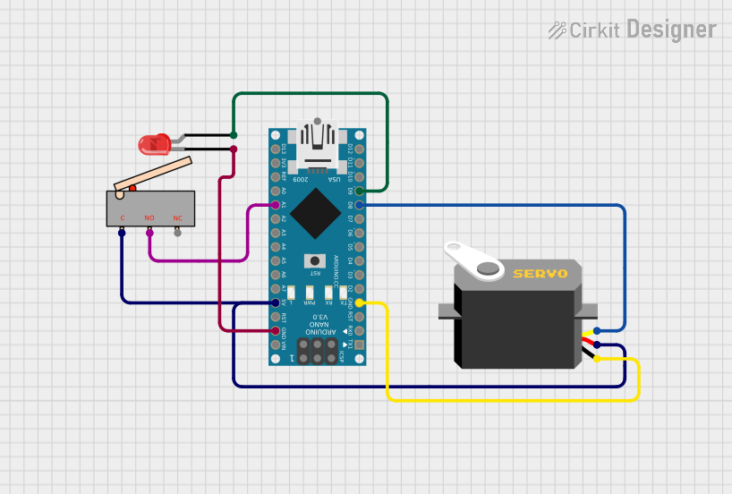
Arduino Nano Controlled Servo with Limit Switch and Indicator LED
Circuit Documentation
Summary of the Circuit
This circuit consists of an Arduino Nano microcontroller, a servo motor, a two-pin red LED, and a limit switch. The Arduino Nano serves as the central processing unit, controlling the servo motor and the LED based on the input from the limit switch. The servo motor is connected to the Arduino for both power and control signals, while the LED is powered by the Arduino and can be turned on or off by the microcontroller. The limit switch is used as an input device to trigger certain actions when activated.
Component List
Arduino Nano
- Description: A compact microcontroller board based on the ATmega328P.
- Purpose: Acts as the central controller for the circuit, interfacing with the servo, LED, and limit switch.
- Pins: D1/TX, D0/RX, RESET, GND, D2, D3, D4, D5, D6, D7, D8, D9, D10, D11/MOSI, D12/MISO, VIN, 5V, A7, A6, A5, A4, A3, A2, A1, A0, AREF, 3V3, D13/SCK.
Servo
- Description: A rotary actuator or linear actuator that allows for precise control of angular or linear position.
- Purpose: Receives control signals from the Arduino to move to a specified position.
- Pins: gnd, vcc, pulse.
LED: Two Pin (red)
- Description: A basic red light-emitting diode.
- Purpose: Provides visual feedback when powered.
- Pins: cathode, anode.
Limit Switch
- Description: An electromechanical device that consists of an actuator mechanically linked to a set of contacts.
- Purpose: Serves as an input to the Arduino, triggering actions when the switch is activated.
- Pins: C, NO, NC.
Wiring Details
Arduino Nano
- GND connected to:
- Servo (gnd)
- LED (cathode)
- D8 connected to Servo (pulse)
- D9 connected to LED (anode)
- 5V connected to:
- Servo (vcc)
- Limit Switch (C)
- A1 connected to Limit Switch (NO)
Servo
- gnd connected to Arduino Nano (GND)
- vcc connected to Arduino Nano (5V)
- pulse connected to Arduino Nano (D8)
LED: Two Pin (red)
- anode connected to Arduino Nano (D9)
- cathode connected to Arduino Nano (GND)
Limit Switch
- C connected to Arduino Nano (5V)
- NO connected to Arduino Nano (A1)
Documented Code
Arduino Nano Code (sketch.ino)
void setup() {
  // put your setup code here, to run once:

}

void loop() {
  // put your main code here, to run repeatedly:

}
Note: The provided code is a template and does not contain any functional code to control the components. It needs to be populated with the appropriate setup and loop code to interact with the servo, LED, and limit switch.