
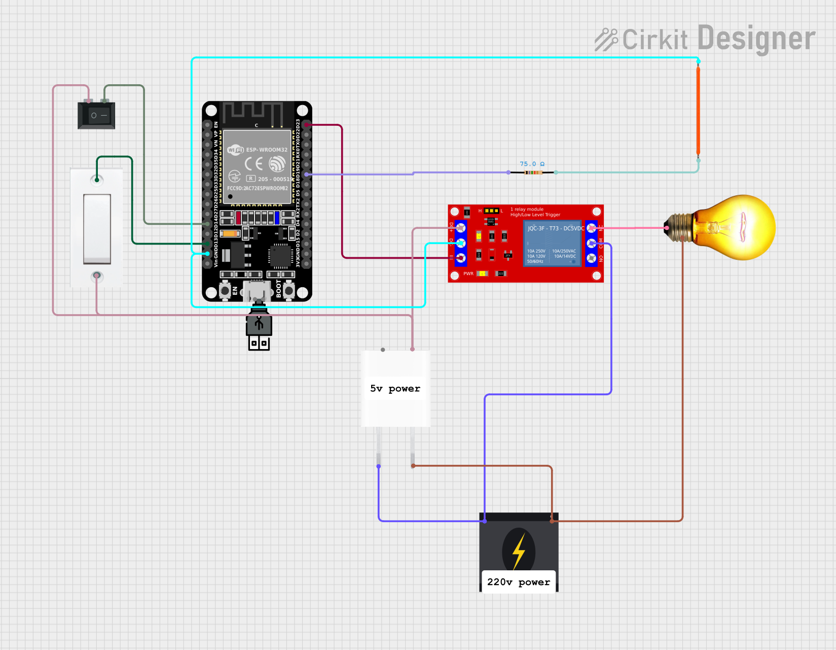
Circuit Documentation
Summary
This circuit is designed to control an AC bulb and an LED filament using an ESP32 microcontroller. The circuit includes a relay module to switch the AC bulb, a resistor to limit current to the LED filament, and switches for manual control. The ESP32 is programmed to connect to a WiFi network and can be controlled remotely via the SinricPro platform.
Component List
AC Bulb
- Description: Standard AC bulb.
- Pins: P (Phase), N (Neutral)
LED Filament 3V
- Description: 3V LED filament.
- Pins: GND, Vcc
1 Channel 5V Relay Module
- Description: Relay module for switching high voltage devices.
- Pins: VCC+, VCC- (GND), IN, N.O. (Normally Open), COM (Common), N.C. (Normally Closed)
Resistor
- Description: 75 Ohms resistor.
- Pins: pin1, pin2
- Properties: Resistance: 75 Ohms
5V Adapter
- Description: Adapter to convert 240V AC to 5V DC.
- Pins: AC In 1, AC In 2, 5V, GND
Flush Switch
- Description: Flush-mounted switch.
- Pins: GND, VCC
Rocker Switch (SPST)
- Description: Single Pole Single Throw (SPST) rocker switch.
- Pins: 1, 2
ESP32 (30 pin)
- Description: ESP32 microcontroller with 30 pins.
- Pins: EN, VP, VN, D34, D35, D32, D33, D25, D26, D27, D14, D12, D13, GND, Vin, D23, D22, TX0, RX0, D21, D19, D18, D5, TX2, RX2, D4, D2, D15, 3V3
240v Power Source
- Description: Standard 240V AC power source.
- Pins: Live, Neutral
USB power
- Description: USB power source.
- Pins: +, -
Wiring Details
AC Bulb
- P (Phase): Connected to N.C. pin of the 1 Channel 5V Relay Module.
- N (Neutral): Connected to Neutral pin of the 240v Power Source.
LED Filament 3V
- GND: Connected to VCC- (GND) pin of the 1 Channel 5V Relay Module and GND pin of the ESP32.
- Vcc: Connected to pin2 of the Resistor.
1 Channel 5V Relay Module
- VCC+: Connected to 5V pin of the 5V Adapter.
- VCC- (GND): Connected to GND pin of the ESP32 and GND pin of the LED Filament 3V.
- IN: Connected to D23 pin of the ESP32.
- N.O. (Normally Open): Not used.
- COM (Common): Connected to Live pin of the 240v Power Source.
- N.C. (Normally Closed): Connected to P (Phase) pin of the AC Bulb.
Resistor
- pin1: Connected to D19 pin of the ESP32.
- pin2: Connected to Vcc pin of the LED Filament 3V.
5V Adapter
- AC In 1: Connected to Neutral pin of the 240v Power Source.
- AC In 2: Connected to Live pin of the 240v Power Source.
- 5V: Connected to VCC+ pin of the 1 Channel 5V Relay Module.
- GND: Not used.
Flush Switch
- GND: Connected to pin1 of the Rocker Switch (SPST).
- VCC: Connected to D13 pin of the ESP32.
Rocker Switch (SPST)
- 1: Connected to GND pin of the Flush Switch.
- 2: Connected to D14 pin of the ESP32.
ESP32 (30 pin)
- EN: Not used.
- VP: Not used.
- VN: Not used.
- D34: Not used.
- D35: Not used.
- D32: Not used.
- D33: Not used.
- D25: Not used.
- D26: Not used.
- D27: Not used.
- D14: Connected to pin2 of the Rocker Switch (SPST).
- D12: Not used.
- D13: Connected to VCC pin of the Flush Switch.
- GND: Connected to VCC- (GND) pin of the 1 Channel 5V Relay Module and GND pin of the LED Filament 3V.
- Vin: Not used.
- D23: Connected to IN pin of the 1 Channel 5V Relay Module.
- D22: Not used.
- TX0: Not used.
- RX0: Not used.
- D21: Not used.
- D19: Connected to pin1 of the Resistor.
- D18: Not used.
- D5: Not used.
- TX2: Not used.
- RX2: Not used.
- D4: Not used.
- D2: Not used.
- D15: Not used.
- 3V3: Not used.
240v Power Source
- Live: Connected to COM pin of the 1 Channel 5V Relay Module and AC In 2 pin of the 5V Adapter.
- Neutral: Connected to N pin of the AC Bulb and AC In 1 pin of the 5V Adapter.
USB power
- +: Not used.
- -: Not used.
Code Documentation
sketch.ino
#ifdef ENABLE_DEBUG
    #define DEBUG_ESP_PORT Serial
    #define NODEBUG_WEBSOCKETS
    #define NDEBUG
#endif

#include <WiFi.h>
#include "SinricPro.h"
#include "SinricProSwitch.h"

#define WIFI_SSID         "Wifi1"
#define WIFI_PASS         "U9mpdfjj3"
#define APP_KEY           "8073da43-50a1-415d-bb7d-09b7d66f7e74"
#define APP_SECRET        "af4bb54f-bab6-41df-88a1-b31308a3dc55-4a2218f5-d905-4700-a956-25b532156dcf"
#define SWITCH_ID         "6772b86f13f98f141618c214"

#define BAUD_RATE         115200               // Change baudrate to your need
#define SwitchPin1        13
#define SwitchPin2        12
#define RelayPin1         23
#define RelayPin2         19
#define wifiLed           2      //D2

int toggleState_1 = 0; // Define integer to remember the toggle state for relay 1
int toggleState_2 = 0; // Define integer to remember the toggle state for relay 2

bool SwitchState_1 = LOW;
bool SwitchState_2 = LOW;
bool myPowerState = false;
unsigned long lastBtnPress = 0;

bool onPowerState1(const String &deviceId, bool &state) {
  Serial.printf("Device %s turned %s (via SinricPro) \\r\\n", deviceId.c_str(), state ? "on" : "off");
  myPowerState = state;
  digitalWrite(RelayPin1, myPowerState ? LOW : HIGH);
  return true; // request handled properly
}

bool onPowerState2(const String &deviceId, bool &state) {
  Serial.printf("Device %s turned %s (via SinricPro) \\r\\n", deviceId.c_str(), state ? "on" : "off");
  myPowerState = state;
  digitalWrite(RelayPin2, myPowerState ? LOW : HIGH);
  return true; // request handled properly
}

void handleButtonPress() {
  unsigned long actualMillis = millis(); // get actual millis() and keep it in variable actualMillis

  if (digitalRead(SwitchPin1) == LOW && SwitchState_1 == LOW && actualMillis - lastBtnPress > 1000) {
    myPowerState = !myPowerState; // flip myPowerState
    digitalWrite(RelayPin1, myPowerState ? LOW : HIGH); // toggle relay state
    SwitchState_1 = HIGH;
    Serial.println("Switch-1 toggled");
    lastBtnPress = actualMillis;
  }

  if (digitalRead(SwitchPin1) == HIGH && SwitchState_1 == HIGH) {
    SwitchState_1 = LOW;
  }

  if (digitalRead(SwitchPin2) == LOW && SwitchState_2 == LOW && actualMillis - lastBtnPress > 1000