
Cirkit Designer
Your all-in-one circuit design IDE
Home /
Project Documentation
Arduino UNO Controlled Dual Servo Rain Sensor System
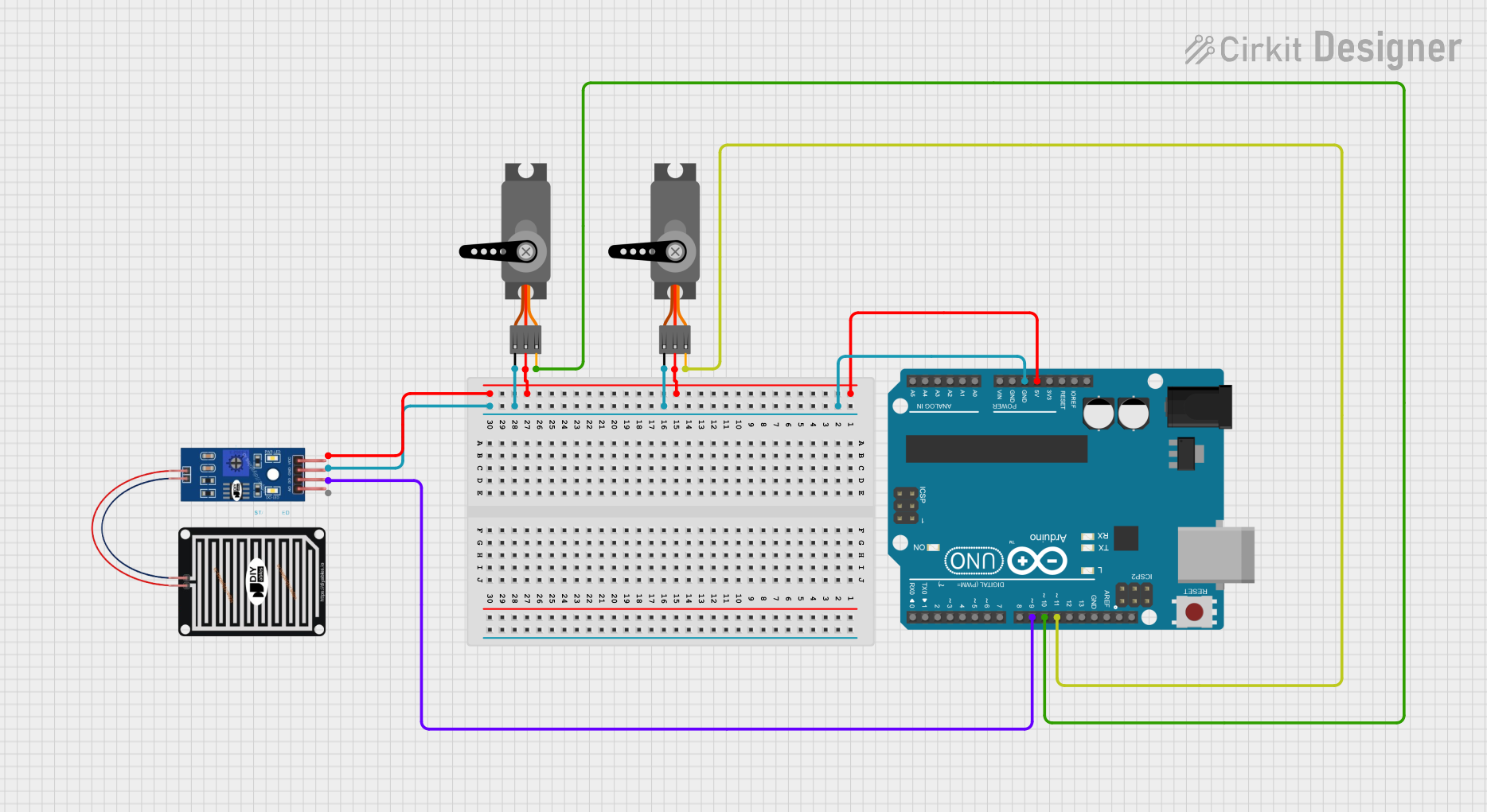
Circuit Documentation
Summary
The circuit in question is designed around an Arduino UNO microcontroller, which serves as the central processing unit. The circuit includes two servo motors and a rain sensor. The Arduino UNO provides power to the servos and the rain sensor, and it also controls the servos via PWM signals. Additionally, the Arduino monitors the digital output (DO) of the rain sensor to detect the presence of rain.
Component List
Arduino UNO
- Description: A microcontroller board based on the ATmega328P.
- Pins Used:
5V: Provides power to other components.GND: Common ground for the circuit.D11: PWM output to control one servo motor.D10: PWM output to control another servo motor.D9: Digital input to read the rain sensor's digital output.
Servo (1st Instance)
- Description: A rotary actuator or linear actuator that allows for precise control of angular or linear position.
- Pins Used:
GND: Ground connection.VCC: Power supply (5V from Arduino UNO).PWM: Pulse Width Modulation input for control signal.
Servo (2nd Instance)
- Description: Identical to the first servo, used for similar purposes.
- Pins Used:
GND: Ground connection.VCC: Power supply (5V from Arduino UNO).PWM: Pulse Width Modulation input for control signal.
RAIN SENSOR
- Description: A sensor that detects rain by measuring the amount of water present on its surface.
- Pins Used:
GRD: Ground connection.VCC: Power supply (5V from Arduino UNO).DO: Digital output that indicates the presence of rain.
Wiring Details
Arduino UNO
5Vconnected to:- Servo (1st Instance)
VCC - Servo (2nd Instance)
VCC - RAIN SENSOR
VCC
- Servo (1st Instance)
GNDconnected to:- Servo (1st Instance)
GND - Servo (2nd Instance)
GND - RAIN SENSOR
GRD
- Servo (1st Instance)
D11connected to Servo (1st Instance)PWMD10connected to Servo (2nd Instance)PWMD9connected to RAIN SENSORDO
Servo (1st Instance)
GNDconnected to Arduino UNOGNDVCCconnected to Arduino UNO5VPWMconnected to Arduino UNOD11
Servo (2nd Instance)
GNDconnected to Arduino UNOGNDVCCconnected to Arduino UNO5VPWMconnected to Arduino UNOD10
RAIN SENSOR
GRDconnected to Arduino UNOGNDVCCconnected to Arduino UNO5VDOconnected to Arduino UNOD9
Documented Code
Arduino UNO Code (sketch.ino)
void setup() {
  // put your setup code here, to run once:

}

void loop() {
  // put your main code here, to run repeatedly:

}
Note: The provided code is a template and does not include specific functionality. It should be populated with the necessary setup and loop code to control the servos and read the rain sensor's digital output.