
ESP32-WROOM-32UE Bluetooth-Controlled Robotic Car with L298N Motor Driver
View and Edit Project In Cirkit Designer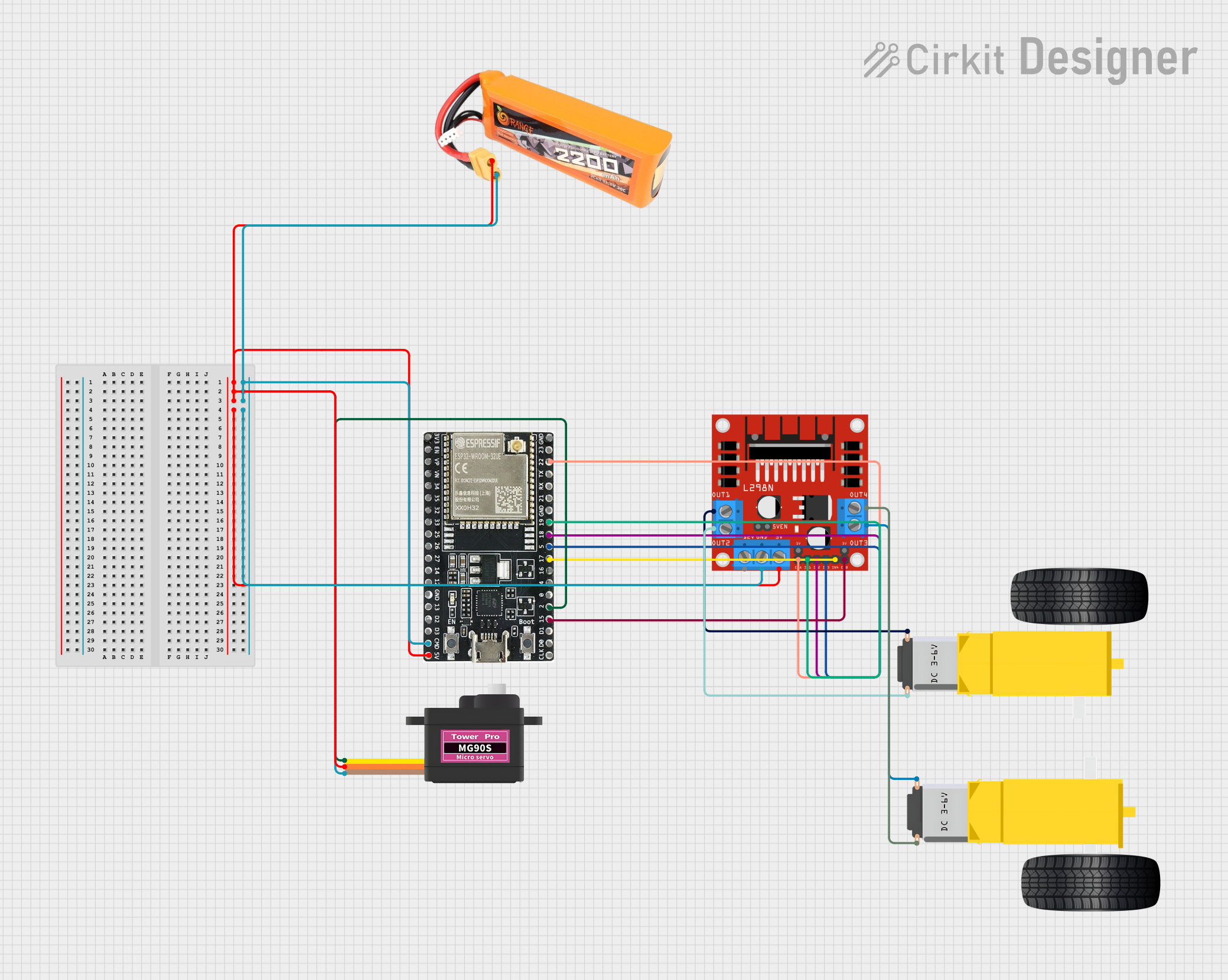
Circuit Documentation
Summary
This circuit is designed to control a remote-controlled car with two DC gearmotors for movement and a servo motor for steering. The ESP32-WROOM-32UE microcontroller is used as the central processing unit, interfacing with a Bluetooth module for remote commands and driving the motors through an L298N DC motor driver. The system is powered by a lipo battery.
Component List
ESP32-WROOM-32UE
- Microcontroller with Bluetooth capability.
- Pins: 3v3, EN, VP, VN, 34, 35, 32, 33, 25, 26, 27, 14, 12, GND, 13, D2, D3, 5V, 23, 22, TX, RX, 21, 19, 18, 5, 17, 16, 4, 0, 2, 15, D1, D0, CKL.
L298N DC Motor Driver
- Dual H-bridge motor driver for controlling up to two DC motors.
- Pins: OUT1, OUT2, 12V, GND, 5V, OUT3, OUT4, 5V-ENA-JMP-I, 5V-ENA-JMP-O, +5V-J1, +5V-J2, ENA, IN1, IN2, IN3, IN4, ENB.
Servomotor MG90S
- Small and lightweight servo motor for steering control.
- Pins: SIG, VCC, GND.
Lipo Battery 2200mAh 30C
- Rechargeable battery providing power to the circuit.
- Pins: VCC, GND.
Gearmotor DC Wheels Right
- DC gearmotor used for the right wheel of the car.
- Pins: PIN1, PIN2.
Gearmotor DC Wheels Left
- DC gearmotor used for the left wheel of the car.
- Pins: PIN1, PIN2.
Wiring Details
ESP32-WROOM-32UE
- 5V connected to Servomotor MG90S VCC, Lipo Battery VCC, and L298N 5V.
- GND connected to Servomotor MG90S GND, Lipo Battery GND, and L298N GND.
- Pin 22 connected to L298N ENA.
- Pin 19 connected to L298N IN1.
- Pin 18 connected to L298N IN2.
- Pin 5 connected to L298N IN3.
- Pin 17 connected to L298N IN4.
- Pin 2 connected to Servomotor MG90S SIG.
- Pin 15 connected to L298N ENB.
L298N DC Motor Driver
- OUT1 connected to Gearmotor DC Wheels Right PIN1.
- OUT2 connected to Gearmotor DC Wheels Right PIN2.
- OUT3 connected to Gearmotor DC Wheels Left PIN1.
- OUT4 connected to Gearmotor DC Wheels Left PIN2.
Servomotor MG90S
- SIG connected to ESP32-WROOM-32UE Pin 2.
- VCC connected to Lipo Battery VCC.
- GND connected to Lipo Battery GND.
Lipo Battery 2200mAh 30C
- VCC connected to ESP32-WROOM-32UE 5V, Servomotor MG90S VCC, and L298N 5V.
- GND connected to ESP32-WROOM-32UE GND, Servomotor MG90S GND, and L298N GND.
Gearmotors DC Wheels (Right and Left)
- Right Gearmotor PIN1 connected to L298N OUT1.
- Right Gearmotor PIN2 connected to L298N OUT2.
- Left Gearmotor PIN1 connected to L298N OUT3.
- Left Gearmotor PIN2 connected to L298N OUT4.
Documented Code
#include <BluetoothSerial.h>
#include <Servo.h>

BluetoothSerial SerialBT;
Servo steeringServo;

const int motorPin1 = 19;
const int motorPin2 = 18;
const int motorPin3 = 5;
const int motorPin4 = 17;
const int enablePinA = 22;
const int enablePinB = 15;
const int steeringPin = 2;

void setup() {
  Serial.begin(115200);
  SerialBT.begin("ESP32_RC_Car"); // Bluetooth device name

  pinMode(motorPin1, OUTPUT);
  pinMode(motorPin2, OUTPUT);
  pinMode(motorPin3, OUTPUT);
  pinMode(motorPin4, OUTPUT);
  pinMode(enablePinA, OUTPUT);
  pinMode(enablePinB, OUTPUT);

  steeringServo.attach(steeringPin);
}

void loop() {
  if (SerialBT.available()) {
    char command = SerialBT.read();
    handleCommand(command);
  }
}

void handleCommand(char command) {
  switch (command) {
    case 'F': // Move forward
      digitalWrite(motorPin1, HIGH);
      digitalWrite(motorPin2, LOW);
      digitalWrite(motorPin3, HIGH);
      digitalWrite(motorPin4, LOW);
      analogWrite(enablePinA, 255);
      analogWrite(enablePinB, 255);
      break;
    case 'B': // Move backward
      digitalWrite(motorPin1, LOW);
      digitalWrite(motorPin2, HIGH);
      digitalWrite(motorPin3, LOW);
      digitalWrite(motorPin4, HIGH);
      analogWrite(enablePinA, 255);
      analogWrite(enablePinB, 255);
      break;
    case 'L': // Turn left
      steeringServo.write(45);
      break;
    case 'R': // Turn right
      steeringServo.write(135);
      break;
    case 'S': // Stop
      digitalWrite(motorPin1, LOW);
      digitalWrite(motorPin2, LOW);
      digitalWrite(motorPin3, LOW);
      digitalWrite(motorPin4, LOW);
      analogWrite(enablePinA, 0);
      analogWrite(enablePinB, 0);
      break;
    default:
      break;
  }
}
This code is responsible for setting up the ESP32 microcontroller to control the motors and servo via Bluetooth commands. It initializes the motor and servo pins, sets up Bluetooth communication, and defines the handleCommand function to interpret the received commands to control the vehicle's movement.