
Circuit Documentation
Summary
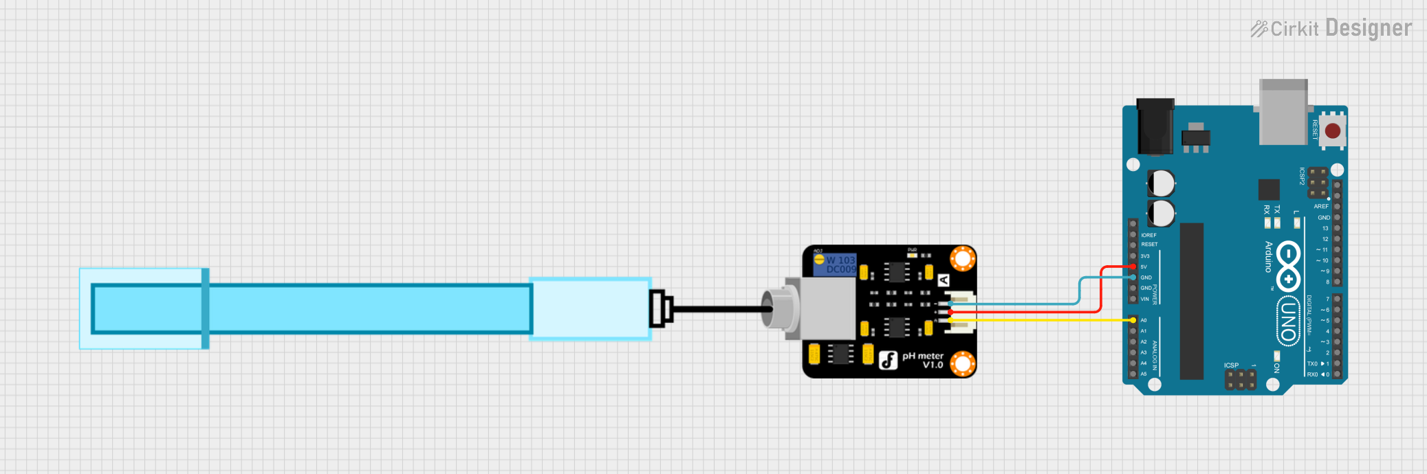
This document provides a detailed overview of a circuit that includes a pH Meter and an Arduino UNO. The pH Meter is used to measure the pH level of a solution, and the Arduino UNO is used to process the signal from the pH Meter. The circuit is designed to read the pH value from the pH Meter and can be further extended to perform various tasks based on the pH level.
Component List
PH Meter
- Description: A sensor used to measure the pH level of a solution.
- Pins: Signal, VCC, GND
Arduino UNO
- Description: A microcontroller board based on the ATmega328P. It has 14 digital input/output pins, 6 analog inputs, a 16 MHz quartz crystal, a USB connection, a power jack, an ICSP header, and a reset button.
- Pins: UNUSED, IOREF, Reset, 3.3V, 5V, GND, Vin, A0, A1, A2, A3, A4, A5, SCL, SDA, AREF, D13, D12, D11, D10, D9, D8, D7, D6, D5, D4, D3, D2, D1, D0
Wiring Details
PH Meter
- Signal: Connected to Arduino UNO pin A0
- VCC: Connected to Arduino UNO pin 5V
- GND: Connected to Arduino UNO pin GND
Arduino UNO
- A0: Connected to PH Meter pin Signal
- 5V: Connected to PH Meter pin VCC
- GND: Connected to PH Meter pin GND
Documented Code
Arduino UNO Code (sketch.ino)
void setup() {
  // put your setup code here, to run once:

}

void loop() {
  // put your main code here, to run repeatedly:

}
Documentation (documentation.txt)
This document provides a comprehensive overview of the circuit, including the components used, their wiring details, and the code for the Arduino UNO. This setup can be used as a foundation for further development and experimentation with pH measurement and control systems.