
Arduino UNO-Based Touch-Activated Treat Dispenser with OLED Display and Servo Mechanism
View and Edit Project In Cirkit Designer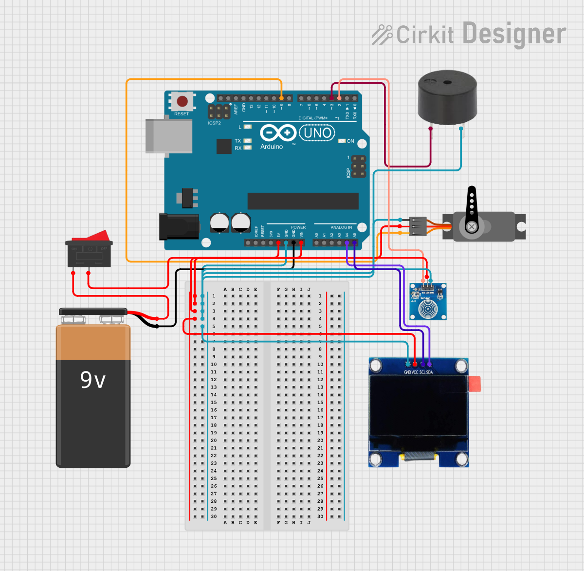
Circuit Documentation
Summary
This circuit is designed to control a servo motor, a buzzer, and an OLED display using an Arduino UNO. The circuit also includes a touch sensor to trigger the servo motor and buzzer. The OLED display shows different messages based on the state of the touch sensor.
Component List
9V Battery
- Description: Provides power to the circuit.
- Pins:
+,-
Arduino UNO
- Description: Microcontroller used to control the components.
- Pins:
UNUSED,IOREF,Reset,3.3V,5V,GND,Vin,A0,A1,A2,A3,A4,A5,SCL,SDA,AREF,D13,D12,D11,D10,D9,D8,D7,D6,D5,D4,D3,D2,D1,D0
Touch Sensor
- Description: Detects touch input to trigger actions.
- Pins:
IO,VCC,GND
Buzzer
- Description: Emits sound when activated.
- Pins:
PIN,GND
OLED 1.3" Display
- Description: Displays messages and images.
- Pins:
GND,VCC,SCL,SDA
Rocker Switch
- Description: Controls the power supply to the Arduino.
- Pins:
1,2
Servo Motor
- Description: Rotates to a specific angle when activated.
- Pins:
GND,VCC,PWM
Wiring Details
9V Battery
- + connected to Rocker Switch pin
1 - - connected to Arduino UNO pin
GND
Arduino UNO
5V connected to:
- Servo Motor pin
VCC - Touch Sensor pin
VCC - OLED 1.3" Display pin
VCC
- Servo Motor pin
GND connected to:
- Servo Motor pin
GND - Touch Sensor pin
GND - Buzzer pin
GND - OLED 1.3" Display pin
GND - 9V Battery pin
-
- Servo Motor pin
Vin connected to Rocker Switch pin
2A4 connected to OLED 1.3" Display pin
SDAA5 connected to OLED 1.3" Display pin
SCLD9 connected to Servo Motor pin
PWMD3 connected to Buzzer pin
PIND2 connected to Touch Sensor pin
IO
Touch Sensor
- VCC connected to Arduino UNO pin
5V - GND connected to Arduino UNO pin
GND - IO connected to Arduino UNO pin
D2
Buzzer
- PIN connected to Arduino UNO pin
D3 - GND connected to Arduino UNO pin
GND
OLED 1.3" Display
- VCC connected to Arduino UNO pin
5V - GND connected to Arduino UNO pin
GND - SCL connected to Arduino UNO pin
A5 - SDA connected to Arduino UNO pin
A4
Rocker Switch
- 1 connected to 9V Battery pin
+ - 2 connected to Arduino UNO pin
Vin
Servo Motor
- VCC connected to Arduino UNO pin
5V - GND connected to Arduino UNO pin
GND - PWM connected to Arduino UNO pin
D9
Code Documentation
#include <Wire.h>
#include <Adafruit_GFX.h>
#include <Adafruit_SH1106.h>
#include <Servo.h>

// OLED display setup
#define OLED_RESET -1
Adafruit_SH1106 display(OLED_RESET);

// Servo setup
Servo myServo;

const int touchPin = 2;
const int buzzerPin = 3;
const int servoPin = 9;

// Lockout variables
bool touchDetected = false;
unsigned long touchStartTime = 0;
const unsigned long treatDisplayDuration = 300;  // 300 ms for "Giving Treats"
const unsigned long waitBeforeReady = 2000;      // 2 seconds waiting phase

// OBECK CAT logo image for OLED
const unsigned char cat_bmp[] PROGMEM = {
  0xff, 0xff, 0xff, 0xff, 0xff, 0xff, 0xc0, 0xff, 0xff, 0xff, 0xff, 0xff, 0xff, 0xc0, 0xff, 0xff,
  0xff, 0xff, 0xff, 0xff, 0xc0, 0xff, 0xff, 0xff, 0xff, 0xff, 0xff, 0xc0, 0xff, 0xff, 0xff, 0xff,
  0xff, 0xff, 0xc0, 0xff, 0xff, 0xc0, 0x00, 0xff, 0xff, 0xc0, 0xff, 0xfe, 0x1f, 0xfc, 0x1f, 0xff,
  0xc0, 0xff, 0xf8, 0xe0, 0x01, 0xc7, 0xff, 0xc0, 0xff, 0xf3, 0x00, 0x00, 0x23, 0xff, 0xc0, 0xff,
  0xe0, 0x00, 0x00, 0x01, 0xff, 0xc0, 0xff, 0xc0, 0x00, 0x00, 0x00, 0xff, 0xc0, 0xff, 0x80, 0x00,
  0x00, 0x00, 0x7f, 0xc0, 0xff, 0x00, 0x00, 0x00, 0x00, 0x3f, 0xc0, 0xfe, 0x00, 0xc0, 0x00, 0xc0,
  0x1f, 0xc0, 0xfe, 0x01, 0xe0, 0x01, 0xe0, 0x1f, 0xc0, 0xfc, 0x04, 0x77, 0xfb, 0x88, 0x0f, 0xc0,
  0xfc, 0x0e, 0x3f, 0xff, 0x1c, 0x07, 0xc0, 0xf8, 0x0f, 0x1c, 0x0e, 0x3c, 0x07, 0xc0, 0xf8, 0x4b,
  0x80, 0x00, 0x74, 0x87, 0xc0, 0xf8, 0x49, 0xc1, 0x20, 0xe4, 0x83, 0xc0, 0xf0, 0xd8, 0xfd, 0x2f,
  0xc4, 0xc3, 0xc0, 0xf8, 0xd9, 0xfd, 0x2f, 0xe6, 0xc7, 0xc0, 0xf8, 0x1f, 0xfd, 0x2f, 0xf6, 0x07,
  0xc0, 0xf8, 0x1f, 0xff, 0xff, 0xfe, 0x07, 0xc0, 0xf8, 0x0f, 0xff, 0xff, 0xfc, 0x87, 0xc0, 0xf0,
  0x8f, 0xff, 0xff, 0xfc, 0x03, 0xc0, 0xe4, 0x0f, 0xff, 0xff, 0xfc, 0x09, 0xc0, 0xec, 0