
Battery-Powered Adjustable Voltage Regulator with Li-ion 18650 Batteries and BMS
View and Edit Project In Cirkit Designer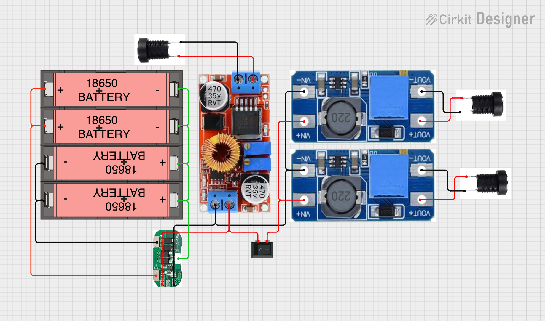
Circuit Documentation
Summary
This document provides a detailed overview of a circuit consisting of multiple Li-ion 18650 batteries, a 2S 30A Battery Management System (BMS), step-up and step-down voltage regulators, a rocker switch, and several DC jacks. The circuit is designed to manage and regulate power from the batteries to various components, ensuring safe and efficient operation.
Component List
Li-ion 18650 Battery
- Description: Rechargeable lithium-ion battery.
- Pins:
+,- - Purpose: Provides power to the circuit.
2S 30A BMS
- Description: Battery Management System for 2-series Li-ion batteries.
- Pins:
B+,B-,BM,P-,T,P+ - Purpose: Manages charging and discharging of the batteries, ensuring safety and efficiency.
Step Up Boost Power Converter, Adjustable Voltage Regulator
- Description: Boosts input voltage to a higher, adjustable output voltage.
- Pins:
VOUT+,VOUT-,VIN+,VIN- - Purpose: Increases the voltage from the battery to the required level for other components.
Regulator Stepdown DC XL4015 CC CV
- Description: Step-down voltage regulator with constant current and constant voltage modes.
- Pins:
IN +,IN -,OUT +,OUT - - Purpose: Reduces the voltage to a lower, stable level for other components.
Rocker Switch (SPST)
- Description: Single Pole Single Throw switch.
- Pins:
1,2 - Purpose: Controls the power flow in the circuit.
DC Buchse
- Description: DC power jack.
- Pins:
Plus,Minus - Purpose: Provides a connection point for external power sources or loads.
Wiring Details
Li-ion 18650 Battery
- Battery 1:
-connected toB-of 2S 30A BMS
- Battery 2:
-connected toB-of 2S 30A BMS+connected to-of Battery 3
- Battery 3:
-connected toBMof 2S 30A BMS+connected toB+of 2S 30A BMS
- Battery 4:
-connected toBMof 2S 30A BMS+connected toB+of 2S 30A BMS
2S 30A BMS
B+connected to+of Battery 3 and Battery 4B-connected to-of Battery 1 and Battery 2BMconnected to-of Battery 3 and Battery 4P-connected toVIN-of both Step Up Boost Power Converters andOUT -of Regulator Stepdown DC XL4015 CC CVP+connected to1of Rocker Switch andOUT +of Regulator Stepdown DC XL4015 CC CV
Step Up Boost Power Converter, Adjustable Voltage Regulator
- Converter 1:
VIN+connected to2of Rocker SwitchVIN-connected toP-of 2S 30A BMSVOUT+connected toPlusof DC Buchse 1VOUT-connected toMinusof DC Buchse 1
- Converter 2:
VIN+connected to2of Rocker SwitchVIN-connected toP-of 2S 30A BMSVOUT+connected toPlusof DC Buchse 3VOUT-connected toMinusof DC Buchse 3
Regulator Stepdown DC XL4015 CC CV
IN +connected toPlusof DC Buchse 2IN -connected toMinusof DC Buchse 2OUT +connected toP+of 2S 30A BMSOUT -connected toP-of 2S 30A BMS
Rocker Switch (SPST)
1connected toP+of 2S 30A BMS2connected toVIN+of both Step Up Boost Power Converters
DC Buchse
- DC Buchse 1:
Plusconnected toVOUT+of Step Up Boost Power Converter 1Minusconnected toVOUT-of Step Up Boost Power Converter 1
- DC Buchse 2:
Plusconnected toIN +of Regulator Stepdown DC XL4015 CC CVMinusconnected toIN -of Regulator Stepdown DC XL4015 CC CV
- DC Buchse 3:
Plusconnected toVOUT+of Step Up Boost Power Converter 2Minusconnected toVOUT-of Step Up Boost Power Converter 2
Code
There is no microcontroller code provided for this circuit.
This documentation provides a comprehensive overview of the circuit, including a summary, detailed component list, wiring details, and code documentation. This should serve as a useful reference for understanding and replicating the circuit.