ESP32 GPS Tracking System with ADXL335 Sensor
Circuit Documentation
Summary
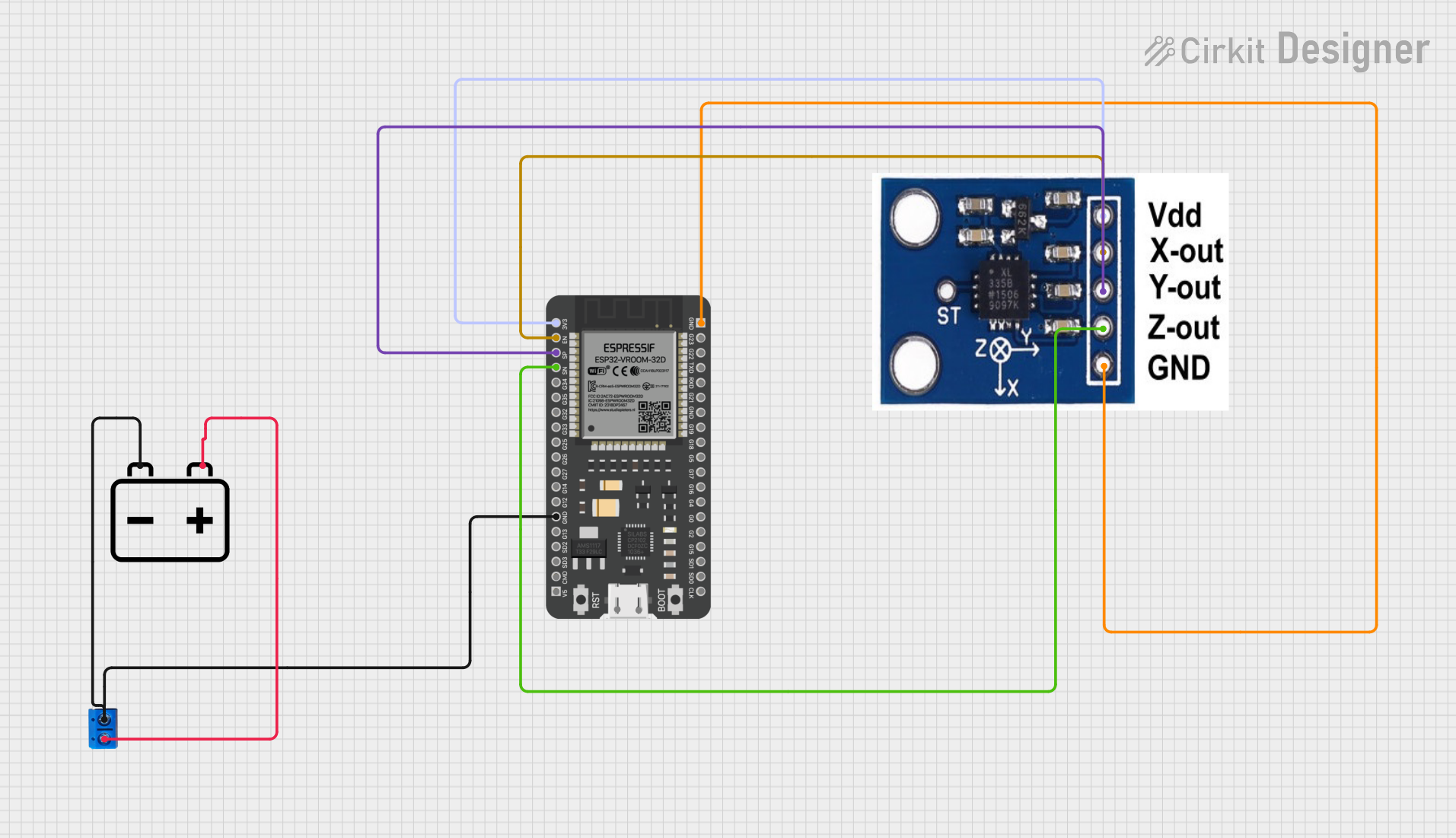
This circuit is designed to interface an ESP32 microcontroller with an ADXXL335 accelerometer. The ESP32 reads data from the accelerometer and can potentially communicate with a GPS module. The circuit is powered by a 12V battery, which is regulated down to the necessary voltage levels for the ESP32 and other components. The wiring includes connections for power, ground, and data communication.
Component List
1. 12V Battery
- Description: A power source providing 12 volts.
- Purpose: Supplies power to the ESP32 and other components in the circuit.
2. ESP32 - 38 Pins
- Description: A powerful microcontroller with Wi-Fi and Bluetooth capabilities.
- Purpose: Acts as the main controller for reading data from the accelerometer and potentially communicating with other devices.
3. Terminal PCB 2 Pin
- Description: A two-pin terminal block for easy connections.
- Purpose: Provides a connection point for the battery and other components.
4. ADXXL335
- Description: A 3-axis accelerometer.
- Purpose: Measures acceleration in three dimensions and provides output to the ESP32.
Wiring Details
1. 12V Battery
Pin -: Connected to the GND pin of the ESP32 and Pin B of the Terminal PCB.
Pin +: Connected to Pin A of the Terminal PCB.
2. ESP32 - 38 Pins
Pin 3V3: Connected to the VCC pin of the ADXXL335.
Pin EN: Connected to the X-OUT pin of the ADXXL335.
Pin SP: Connected to the Y-OUT pin of the ADXXL335.
Pin SN: Connected to the Z-OUT pin of the ADXXL335.
Pin GND: Connected to the GND pin of the ADXXL335 and Pin B of the Terminal PCB.
3. Terminal PCB 2 Pin
Pin A: Connected to the + pin of the 12V Battery.
Pin B: Connected to the GND pin of the ESP32 and the - pin of the 12V Battery.
4. ADXXL335
Pin VCC: Connected to the 3V3 pin of the ESP32.
Pin GND: Connected to the GND pin of the ESP32 and Pin B of the Terminal PCB.
Pin X-OUT: Connected to the EN pin of the ESP32.
Pin Y-OUT: Connected to the SP pin of the ESP32.
Pin Z-OUT: Connected to the SN pin of the ESP32.
Documented Code
#include <Adafruit_ADXL343.h>
#include <TinyGPS++.h>
#include <SoftwareSerial.h>

TinyGPSPlus gps;
SoftwareSerial ss(16, 17); // RX, TX

void setup() {
  Serial.begin(115200);
  ss.begin(9600);
  Serial.println("GPS Tracking Initialized");
}

void loop() {
  while (ss.available() > 0) {
    gps.encode(ss.read());
    if (gps.location.isUpdated()) {
      Serial.print("Latitude: ");
      Serial.println(gps.location.lat(), 6);
      Serial.print("Longitude: ");
      Serial.println(gps.location.lng(), 6);
      Serial.print("Altitude: ");
      Serial.println(gps.altitude.meters());
      Serial.print("Speed: ");
      Serial.println(gps.speed.kmph());
      Serial.print("Satellites: ");
      Serial.println(gps.satellites.value());
    }
  }
}
This code initializes the ESP32 to read GPS data from a connected GPS module and prints the location, altitude, speed, and number of satellites to the Serial Monitor.