
Arduino Nano Battery-Powered Buzzer and LED Control with Pushbutton
View and Edit Project In Cirkit Designer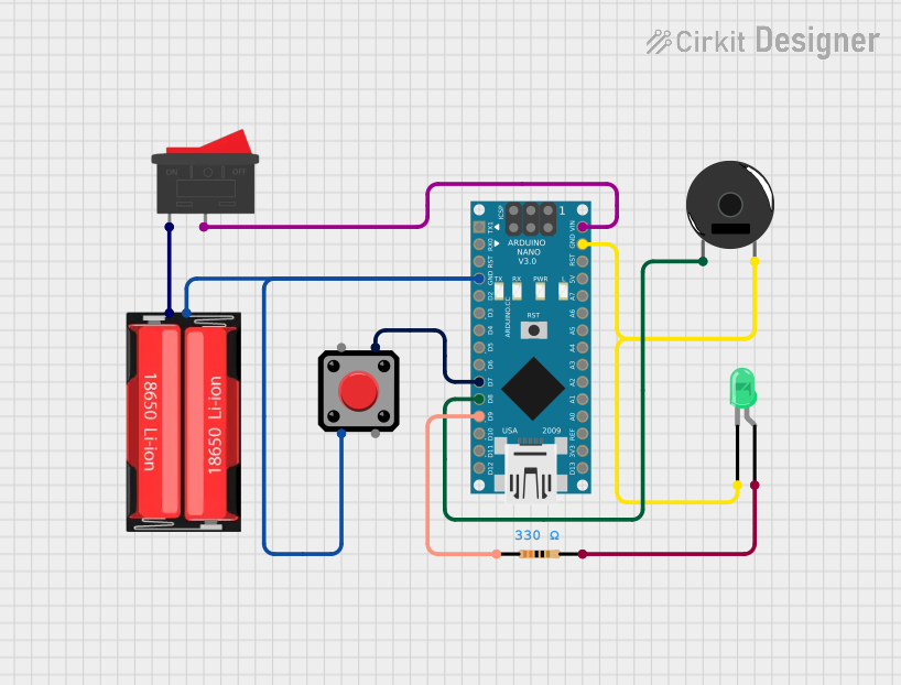
Circuit Documentation
Summary
This circuit consists of an Arduino Nano microcontroller, a Piezo Buzzer, a green LED, a resistor, a pushbutton, a 18650 Li-Ion battery, and a rocker switch. The circuit is designed to interact with the pushbutton and control the LED and Piezo Buzzer based on the Arduino Nano's programming.
Component List
Arduino Nano
- Description: A small, complete, and breadboard-friendly board based on the ATmega328P.
- Pins: D1/TX, D0/RX, RESET, GND, D2, D3, D4, D5, D6, D7, D8, D9, D10, D11/MOSI, D12/MISO, VIN, 5V, A7, A6, A5, A4, A3, A2, A1, A0, AREF, 3V3, D13/SCK
Piezo Buzzer
- Description: An electronic device that produces a tone, alarm, or sound.
- Pins: pin 1, pin 2
LED: Two Pin (green)
- Description: A green light-emitting diode.
- Pins: cathode, anode
Resistor
- Description: A 330 Ohm resistor used to limit current.
- Pins: pin1, pin2
- Properties:
- Resistance: 330 Ohms
Pushbutton
- Description: A simple pushbutton switch.
- Pins: Pin 2, Pin 1, Pin 3, Pin 4
18650 Li-Ion
- Description: A rechargeable lithium-ion battery.
- Pins: Positive, Negative
Rocker Switch
- Description: A switch that can be toggled between two states.
- Pins: 1, 2
Wiring Details
Arduino Nano
- GND is connected to the Negative pin of the 18650 Li-Ion battery and Pin 2 of the pushbutton.
- D7 is connected to Pin 4 of the pushbutton.
- D8 is connected to pin 1 of the Piezo Buzzer.
- D9 is connected to pin1 of the resistor.
- VIN is connected to pin 2 of the rocker switch.
- GND is also connected to the cathode of the green LED and pin 2 of the Piezo Buzzer.
Piezo Buzzer
- pin 1 is connected to D8 of the Arduino Nano.
- pin 2 is connected to GND of the Arduino Nano and the cathode of the green LED.
LED: Two Pin (green)
- cathode is connected to GND of the Arduino Nano and pin 2 of the Piezo Buzzer.
- anode is connected to pin2 of the resistor.
Resistor
- pin1 is connected to D9 of the Arduino Nano.
- pin2 is connected to the anode of the green LED.
Pushbutton
- Pin 2 is connected to GND of the Arduino Nano and the Negative pin of the 18650 Li-Ion battery.
- Pin 4 is connected to D7 of the Arduino Nano.
18650 Li-Ion
- Positive is connected to pin 1 of the rocker switch.
- Negative is connected to GND of the Arduino Nano and Pin 2 of the pushbutton.
Rocker Switch
- pin 1 is connected to the Positive pin of the 18650 Li-Ion battery.
- pin 2 is connected to VIN of the Arduino Nano.
Code Documentation
Arduino Nano Code
void setup() {
  // put your setup code here, to run once:

}

void loop() {
  // put your main code here, to run repeatedly:

}
This code is a basic template for the Arduino Nano. The setup() function is where you initialize your settings, and the loop() function is where you place the main code that runs repeatedly.
Additional Documentation
This section is reserved for any additional documentation or notes related to the code or circuit.