
Circuit Documentation
Summary
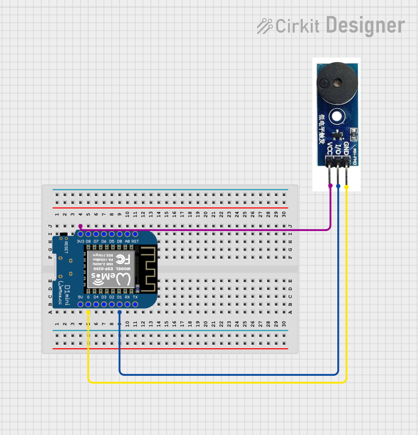
This document provides a detailed overview of a simple circuit consisting of a Wemos D1 Mini microcontroller and an Active Buzzer Module. The Wemos D1 Mini is used to control the buzzer, which can be activated through a digital output pin. The circuit is powered by the 3.3V supply from the Wemos D1 Mini.
Component List
Wemos D1 Mini
- Description: A compact microcontroller board based on the ESP8266 WiFi module.
- Pins: RST, A0, D0, D5, D6, D7, D8, 3V3, 5V, G, D4, D3, D2, D1, RX, TX
- Purpose in Circuit: Acts as the main controller, providing power and control signals to the Active Buzzer Module.
Active Buzzer Module
- Description: A module that produces sound when a voltage is applied to its input pin.
- Pins: GND, I/O, VCC
- Purpose in Circuit: Generates sound when activated by the Wemos D1 Mini.
Wiring Details
Wemos D1 Mini
- 3V3: Connected to VCC of the Active Buzzer Module
- G: Connected to GND of the Active Buzzer Module
- D1: Connected to I/O of the Active Buzzer Module
Active Buzzer Module
- VCC: Connected to 3V3 of the Wemos D1 Mini
- GND: Connected to G of the Wemos D1 Mini
- I/O: Connected to D1 of the Wemos D1 Mini
Code
There is no code provided for this circuit.